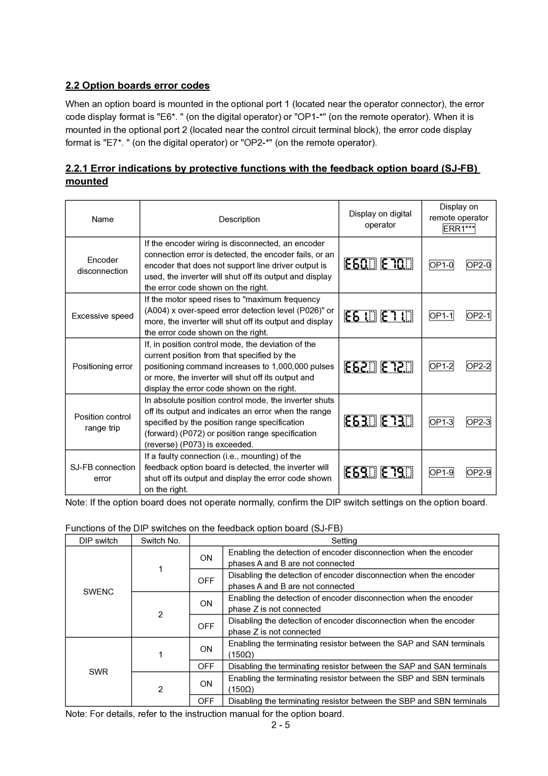
2.2 Option boards error codes
When an option board is mounted in the optional port 1 (located near the operator connector), the error code display format is "E6*. " (on the digital operator) or
2.2.1Error indications by protective functions with the feedback option board
Name | Description | |
|
| |
| If the encoder wiring is disconnected, an encoder | |
Encoder | connection error is detected, the encoder fails, or an | |
encoder that does not support line driver output is | ||
disconnection | ||
used, the inverter will shut off its output and display | ||
| ||
| the error code shown on the right. | |
| If the motor speed rises to "maximum frequency | |
Excessive speed | (A004) x | |
more, the inverter will shut off its output and display | ||
| ||
| the error code shown on the right. | |
| If, in position control mode, the deviation of the | |
| current position from that specified by the | |
Positioning error | positioning command increases to 1,000,000 pulses | |
| or more, the inverter will shut off its output and | |
| display the error code shown on the right. | |
| In absolute position control mode, the inverter shuts | |
Position control | off its output and indicates an error when the range | |
specified by the position range specification | ||
range trip | ||
(forward) (P072) or position range specification | ||
| ||
| (reverse) (P073) is exceeded. | |
| If a faulty connection (i.e., mounting) of the | |
feedback option board is detected, the inverter will | ||
error | shut off its output and display the error code shown | |
| on the right. |
Display on digital
operator
Display on
remote operator
ERR1***
![]()
![]() OP2-0
OP2-0
![]()
![]() OP2-1
OP2-1
![]()
![]() OP2-2
OP2-2
![]()
![]() OP2-3
OP2-3
![]()
![]() OP2-9
OP2-9
Note: If the option board does not operate normally, confirm the DIP switch settings on the option board. Functions of the DIP switches on the feedback option board
DIP switch | Switch No. |
| Setting |
|
| ON | Enabling the detection of encoder disconnection when the encoder |
|
| phases A and B are not connected | |
| 1 |
| |
| OFF | Disabling the detection of encoder disconnection when the encoder | |
|
| ||
|
| phases A and B are not connected | |
SWENC |
|
| |
| ON | Enabling the detection of encoder disconnection when the encoder | |
|
| ||
|
| phase Z is not connected | |
| 2 |
| |
| OFF | Disabling the detection of encoder disconnection when the encoder | |
|
| ||
|
| phase Z is not connected | |
|
|
| |
|
| ON | Enabling the terminating resistor between the SAP and SAN terminals |
| 1 | (150Ω) | |
|
| ||
SWR |
| OFF | Disabling the terminating resistor between the SAP and SAN terminals |
| ON | Enabling the terminating resistor between the SBP and SBN terminals | |
|
| ||
| 2 | (150Ω) | |
|
| ||
|
| OFF | Disabling the terminating resistor between the SBP and SBN terminals |
Note: For details, refer to the instruction manual for the option board. 2 - 5
