
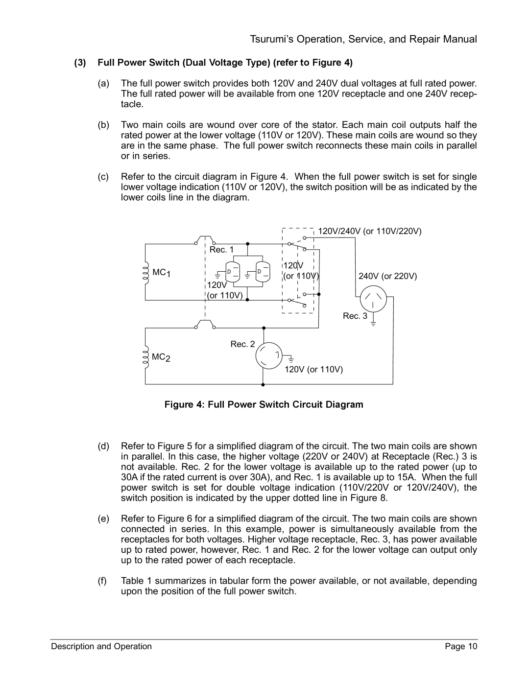
TPG-4300H-DX, TPG-6000H-DX, TPG-7000H-DXE, TPG-2900H-DX specifications
Honda Power Equipment has long been synonymous with reliability and innovation in the realm of portable power solutions. Among its impressive lineup, the TPG series showcases a range of generators designed to meet diverse power requirements. The TPG-7000H-DXE, TPG-2900H-DX, TPG-6000H-DX, and TPG-4300H-DX are standout models equipped with cutting-edge technologies, exceptional features, and robust characteristics.The TPG-7000H-DXE is a powerhouse, providing a maximum output of 7000 watts. This generator is equipped with a Honda GX390 engine, known for its durability and fuel efficiency. A key feature is its advanced inverter technology, which delivers clean and stable power, making it suitable for sensitive electronic devices. Additionally, the unit is designed with a large fuel tank, enabling extended runtimes and reducing the frequency of refueling. Portability is another hallmark of the TPG-7000H-DXE, featuring ergonomic handles and wheels for easy transport.
Next in line, the TPG-2900H-DX is a compact yet powerful generator, ideal for recreational activities or as a backup power source. With a maximum output of 2900 watts, this model also incorporates an inverter system to ensure clean power delivery. It boasts low noise levels, making it a perfect choice for camping or tailgating. The ease of use is enhanced by its straightforward control panel and electric start option, allowing users to power up quickly and efficiently.
The TPG-6000H-DX offers a balance between power and portability, with a maximum output of 6000 watts. This generator features an innovative automatic voltage regulator that ensures stability across varying loads. The design includes a heavy-duty frame that provides durability while safeguarding internal components. With its versatile outlet configuration, users can connect multiple devices simultaneously, making it ideal for job sites or home use.
Lastly, the TPG-4300H-DX targets users who require reliable power in a mid-range class. This model delivers 4300 watts and incorporates user-friendly features like a simple recoil start and low-oil shutdown for engine protection. Its compact design and robust wheels facilitate easy movement, while the durable construction ensures it withstands diverse weather conditions.
In summary, Honda's TPG series exemplifies excellence in power generation, featuring advanced technology, engineered for robustness, and tailored for versatility. Whether for backup power, recreational use, or professional applications, models like the TPG-7000H-DXE, TPG-2900H-DX, TPG-6000H-DX, and TPG-4300H-DX meet the power demands of today's users.