FOR TSURUMI TPG-SERIES
OPERATION, SERVICE, AND
REPAIR MANUAL
PORTABLE GENERATORS
LIMITED WARRANTY
Tsurumi Manufacturing Co., Ltd
TABLE OF CONTENTS
Tsurumi’s Operation, Service, and Repair Manual
1. INTRODUCTION
A. PRECAUTIONS AND PLACARDS
Tsurumi’s Operation, Service, and Repair Manual
FUEL WARNING PLACARD
AIR CLEANER MAINTENANCE
DATA PLATE
HOT MUFFLER & EXHAUST PLACARD
B. SAFETY PRECAUTIONS
Tsurumi’s Operation, Service, and Repair Manual
C. SPECIFICATIONS/KEY FEATURES
Tsurumi’s Operation, Service, and Repair Manual
•100% Copper Windings…for long life
2. DESCRIPTION AND OPERATION
A.PHYSICAL DESCRIPTION
Tsurumi’s Operation, Service, and Repair Manual
Tsurumi’s Operation, Service, and Repair Manual
2Description of Generator
4Description of the Fuel Tank
Tsurumi’s Operation, Service, and Repair Manual
3Description of the Engine
5Description of the Front Panel
1Generation of No-LoadVoltage refer to Figure
B.FUNCTIONAL DESCRIPTION
Tsurumi’s Operation, Service, and Repair Manual
2Voltage Fluctuations Under Load refer to Figure
Tsurumi’s Operation, Service, and Repair Manual
Figure 4: Full Power Switch Circuit Diagram
Tsurumi’s Operation, Service, and Repair Manual
Switch
B.DC CIRCUIT CONTROLS
3. OPERATING INSTRUCTIONS
A.OPERATING CONTROLS
Tsurumi’s Operation, Service, and Repair Manual
LEGEND
Tsurumi’s Operation, Service, and Repair Manual
Figure 7: Model TPG-2900H-DX
Figure 8: Model TPG-4300H-DX
Figure 9: Model TPG-6000H-DX
Tsurumi’s Operation, Service, and Repair Manual
LEGEND
LEGEND
C. CHECK THE ENGINE OIL LEVEL
Tsurumi’s Operation, Service, and Repair Manual
D. CHECK ENGINE FUEL
Tsurumi’s Operation, Service, and Repair Manual
E. PRE-STARTCHECKS
F.STARTING & OPERATING THE ENGINE
Tsurumi’s Operation, Service, and Repair Manual
G. USING THE GENERATOR
H.AC APPLICATION
Tsurumi’s Operation, Service, and Repair Manual
Tsurumi’s Operation, Service, and Repair Manual
BDual Voltage Type
Available Receptacles With Full Power Switch On
I.STOPPING THE GENERATOR
Tsurumi’s Operation, Service, and Repair Manual
Table
M. WATTAGE INFORMATION
J.OIL ALERT
L.STOPPING THE ENGINE
Tsurumi’s Operation, Service, and Repair Manual
Applicable Wattage w
Tsurumi’s Operation, Service, and Repair Manual
Table Wattage Chart
Applicable Wattage W
4. MAINTENANCE
Tsurumi’s Operation, Service, and Repair Manual
Tsurumi’s Operation, Service, and Repair Manual
B. AIR CLEANER SERVICE
A.CHANGING ENGINE OIL
Figure 16: Draining Engine Oil
C. SEDIMENT CUP CLEANING
D. CLEANING AND ADJUSTING SPARK PLUG
Tsurumi’s Operation, Service, and Repair Manual
Tsurumi’s Operation, Service, and Repair Manual
Figure 19: Spark Plug Gap
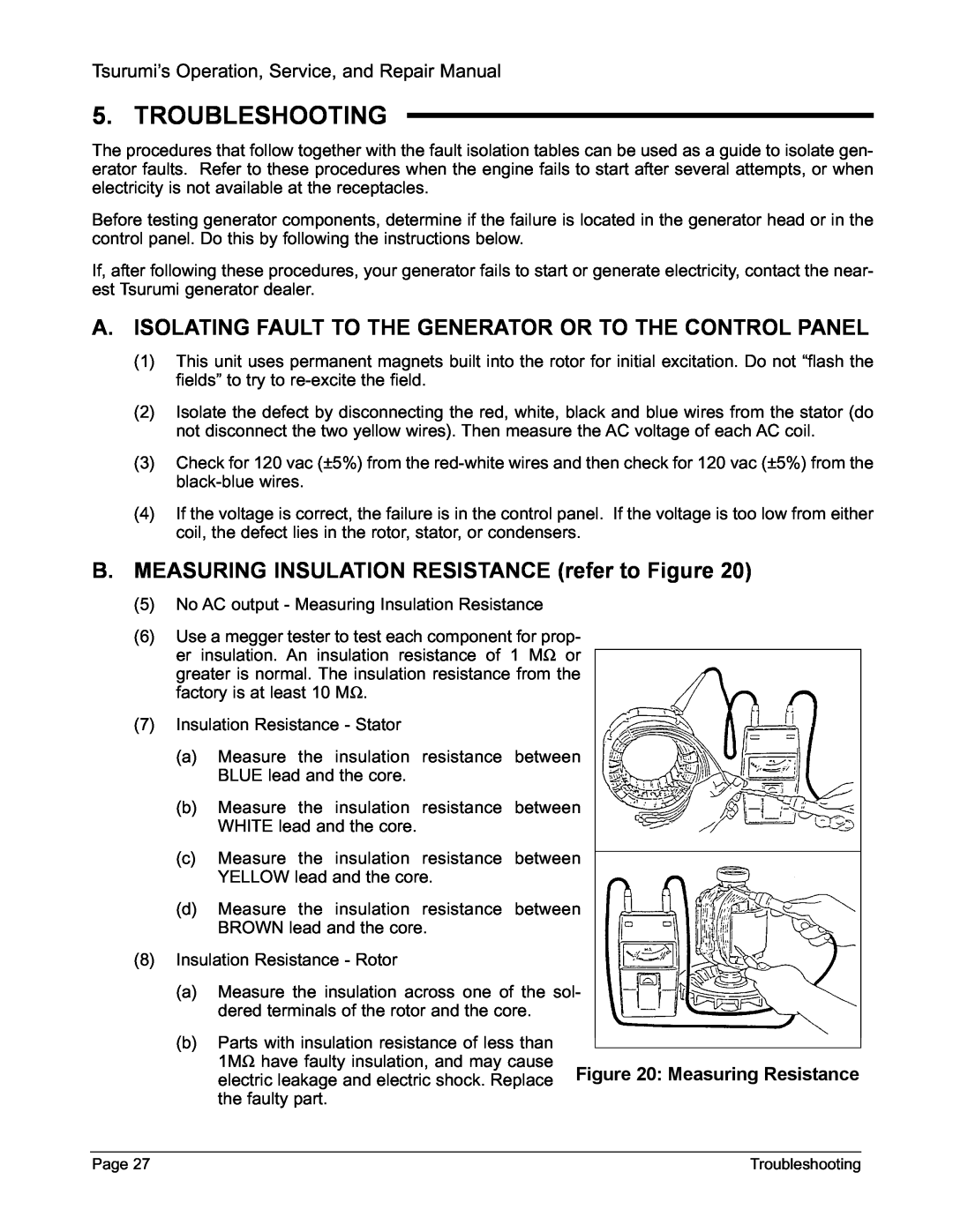
5. TROUBLESHOOTING
Tsurumi’s Operation, Service, and Repair Manual
C. ELECTRICAL LIMITS REFERENCE CHART
Tsurumi’s Operation, Service, and Repair Manual
Table 7: Fault Isolation Procedures
D. TROUBLESHOOTING CHARTS
Tsurumi’s Operation, Service, and Repair Manual
FAULT
refer to COMPONENT REPLACEMENT for
Tsurumi’s Operation, Service, and Repair Manual
FAULT
PROBABLE CAUSE
Tsurumi’s Operation, Service, and Repair Manual
Troubleshooting
Page
Tsurumi’s Operation, Service, and Repair Manual
No DC output
Tsurumi’s Operation, Service, and Repair Manual
Engine speed does
Tsurumi’s Operation, Service, and Repair Manual
Troubleshooting
Page
E. WIRING DIAGRAMS
Tsurumi’s Operation, Service, and Repair Manual
CONTROL BOX
CONTROL BOX
Wiring Diagram - Model TPG-6000H-DX
CONTROL BOX
Tsurumi’s Operation, Service, and Repair Manual
CONTROL BOX
6. REMOVAL/INSTALLATION
Tsurumi’s Operation, Service, and Repair Manual
A. REPLACEMENT OF BATTERY
Tsurumi’s Operation, Service, and Repair Manual
B. REMOVAL/INSTALLATION OF BATTERY ENCLOSURE
Tsurumi’s Operation, Service, and Repair Manual
C.REPLACEMENT OF ENGINE MUFFLER
Tsurumi’s Operation, Service, and Repair Manual
Figure 22: Battery Enclosure Exploded View
Tsurumi’s Operation, Service, and Repair Manual
Figure 23: Replacement of Muffler
Tsurumi’s Operation, Service, and Repair Manual
Figure 24: Replacement of Muffler
Model TPG-2900H-DX
E. REPLACEMENT OF FUEL TANK
Tsurumi’s Operation, Service, and Repair Manual
Tsurumi’s Operation, Service, and Repair Manual
H-13 H-2
Tsurumi’s Operation, Service, and Repair Manual
Figure 26: Draining Fuel from Fuel Tank
Tsurumi’s Operation, Service, and Repair Manual
9Remove four frame bolts 31 from front panel
Tsurumi’s Operation, Service, and Repair Manual
•Model TPG-2900H-DXuses four vibration mounts of two different part numbers. Two vibration
Tsurumi’s Operation, Service, and Repair Manual
H-9 H-10 H-5
G. REPLACEMENT OF GENERATOR STATOR
Tsurumi’s Operation, Service, and Repair Manual
Figure 28: Replacement of Stator
H. REPLACEMENT OF ROTOR BEARING
Tsurumi’s Operation, Service, and Repair Manual
I.REPLACEMENT OF ROTOR
Tsurumi’s Operation, Service, and Repair Manual
Figure 29: Bearing Puller in Use
Tsurumi’s Operation, Service, and Repair Manual
Figure 30: Removal of Through Bolt
Figure 31: Pouring Oil in Rotor Shaft
Figure 32: Wrapping Bolt with Tape
Tsurumi’s Operation, Service, and Repair Manual
Removal/Installation
Wind tape on bolt
Tsurumi’s Operation, Service, and Repair Manual
Replacement of Rotor Bearing
Figure 34: Front Cover Bolts
J.REPLACEMENT OF FRONT PANEL COMPONENTS
Tsurumi’s Operation, Service, and Repair Manual
Tsurumi’s Operation, Service, and Repair Manual
Figure 35: Front Panel and Control Box Components
Tsurumi’s Operation, Service, and Repair Manual
5Engine Start Key Switch TPG-7000H-DXE
Tsurumi’s Operation, Service, and Repair Manual
Figure 36: Front Panel and Control Box Components
Tsurumi’s Operation, Service, and Repair Manual
11Full-powerSwitch
7. STORAGE INSTRUCTIONS
Tsurumi’s Operation, Service, and Repair Manual
B. ORDERING PARTS
8. REPLACEMENT PARTS
A. INTRODUCTION
Tsurumi’s Operation, Service, and Repair Manual
Tsurumi’s Operation, Service, and Repair Manual
Exploded View - Generator - Model TPG-2900H-DX
Part
Tsurumi’s Operation, Service, and Repair Manual
Parts List – Generator – Model TPG-2900H-DX
Number
Tsurumi’s Operation, Service, and Repair Manual
Exploded View - Front Panel - Model TPG-2900H-DX
Part
Tsurumi’s Operation, Service, and Repair Manual
Parts List – Front Panel – Model TPG-2900H-DX
Number
Tsurumi’s Operation, Service, and Repair Manual
Exploded View - Generator - Model TPG-4300H-DX
Part
Tsurumi’s Operation, Service, and Repair Manual
Parts List – Generator – Model TPG-4300H-DX
Number
Tsurumi’s Operation, Service, and Repair Manual
Exploded View - Front Panel - Model TPG-4300H-DX
Part
Tsurumi’s Operation, Service, and Repair Manual
Parts List – Front Panel – Model TPG-4300H-DX
Number
Tsurumi’s Operation, Service, and Repair Manual
Exploded View - Generator - Model TPG-6000H-DX
Part
Tsurumi’s Operation, Service, and Repair Manual
Parts List – Generator – Model TPG-6000H-DX
Number
Tsurumi’s Operation, Service, and Repair Manual
Exploded View - Front Panel - Model TPG-6000H-DX
Part
Tsurumi’s Operation, Service, and Repair Manual
Parts List – Front Panel – Model TPG-6000H-DX
Number
Tsurumi’s Operation, Service, and Repair Manual
Exploded View - Generator - Model TPG-7000H-DXE
Part
Tsurumi’s Operation, Service, and Repair Manual
Parts List – Generator – Model TPG-7000H-DXE
Number
Tsurumi’s Operation, Service, and Repair Manual
Exploded View - Front Panel - Model TPG-7000H-DXE
Part
Tsurumi’s Operation, Service, and Repair Manual
Parts List – Front Panel – Model TPG-7000H-DXE
Number
Part
Description
Number
TSURUMI MODEL TPG-7000H-DXE PORTABLE GENERATOR
APPENDIX A BATTERY ENCLOSURE KIT
ASSEMBLY AND INSTALLATION INSTRUCTIONS FOR
Tsurumi’s Operation, Service, and Repair Manual
Tsurumi’s Operation, Service, and Repair Manual
ASSEMBLY AND INSTALLATION INSTRUCTIONS
FOR TSURUMI PORTABLE GENERATOR BATTERY ENCLOSURE
CHECK KIT CONTENTS
Tsurumi’s Operation, Service, and Repair Manual
INSTALLATION OF BATTERY ENCLOSURE
INSTALLATION OF BATTERY
Tsurumi’s Operation, Service, and Repair Manual
INSTALLATION INSTRUCTIONS
APPENDIX B PGWK-100WHEEL KIT
Appendix B
WHEEL KIT INSTALLATION INSTRUCTIONS
FOR TSURUMI GENERATORS AND PUMPS
Tsurumi’s Operation, Service, and Repair Manual
INSTALL AXLE ON TRASH PUMP
Tsurumi’s Operation, Service, and Repair Manual
INSTALL AXLE ON GENERATOR
INSTALL WHEELS
Tsurumi’s Operation, Service, and Repair Manual
APPENDIX C PGWK-200WHEEL KIT
INSTALLATION INSTRUCTIONS
Page C-1
Installation Instructions
Before Installation
Completed Chart
Tsurumi’s Operation, Service, and Repair Manual
Tsurumi’s Operation, Service, and Repair Manual
Step 1 - Install Axle Assembly and Wheels
Step 2 - Install Handles
Fig.