User’s Guide
Trademarks
Disclaimer
Table of Contents
Using the Dolphin 7900 Terminal
Settings
Wireless LAN Communications with 802.11b
Wireless WAN Wwan Communications with GSM/GPRS
Applications
Dolphin 7900 ChargeBase
Dolphin 7900 Series Mobile Computer User’s Guide
Overview
Introduction
Required Safety Labels
Laser Safety Label
Location
Parameter Specification
802.11b
Dolphin 7900 Series Wlan 802.11b or Wpan Bluetooth Radio
Bluetooth
802.11b and Bluetooth
GSM and 802.11b
GSM and Bluetooth
GSM, 802.11b, and Bluetooth
Dolphin 7900 Series Wwan Radio GSM MC-45 & MC-46
Dolphin 7900 Series Batch Terminal
FCC Compliance
RF, Regulatory, and Safety Agency Approvals for GSM MC-45
RF, Regulatory, and Safety Agency Approvals for GSM MC-46
Parameter
Microwaves
Care and Cleaning of the Dolphin Terminal
Memory
Getting Started
Data Input
Imaging
Dolphin 7900 Radio Configuration Options
Standard Configurations
Custom Configurations
Dolphin 7900 Series Peripherals
Dolphin 7900 Accessories
Unpack the Carton and Verify its Contents
Using the Dolphin 7900 for the First Time
To Remove the Main Battery Pack
Installing the Main Battery Pack
Dolphin 7900 HomeBase see Dolphin 7900 Mobile Base see
Charging with Dolphin Peripherals
Align the Screen
Set the Time Zone
Verify Operations with Demos
Hard Reset Cold Boot
Resetting the Terminal
Suspend Mode
Soft Reset Warm Boot
Dolphin 7900 Series Mobile Computer User’s Guide
Hardware Overview
System Features
PocketPC
Front Panel Features
Scan LED
Audio Jack
Speaker
IrDA Port
Back Panel Features
Hand Strap Slot
Access Door
Battery
Image Engine Window
SIM Card
Side Panel Features
Opening the Access Door
Programmable Side Button
MSD SIM
Installing a Mini-SD Card
Replacing the Access Door
Installing a SIM Card
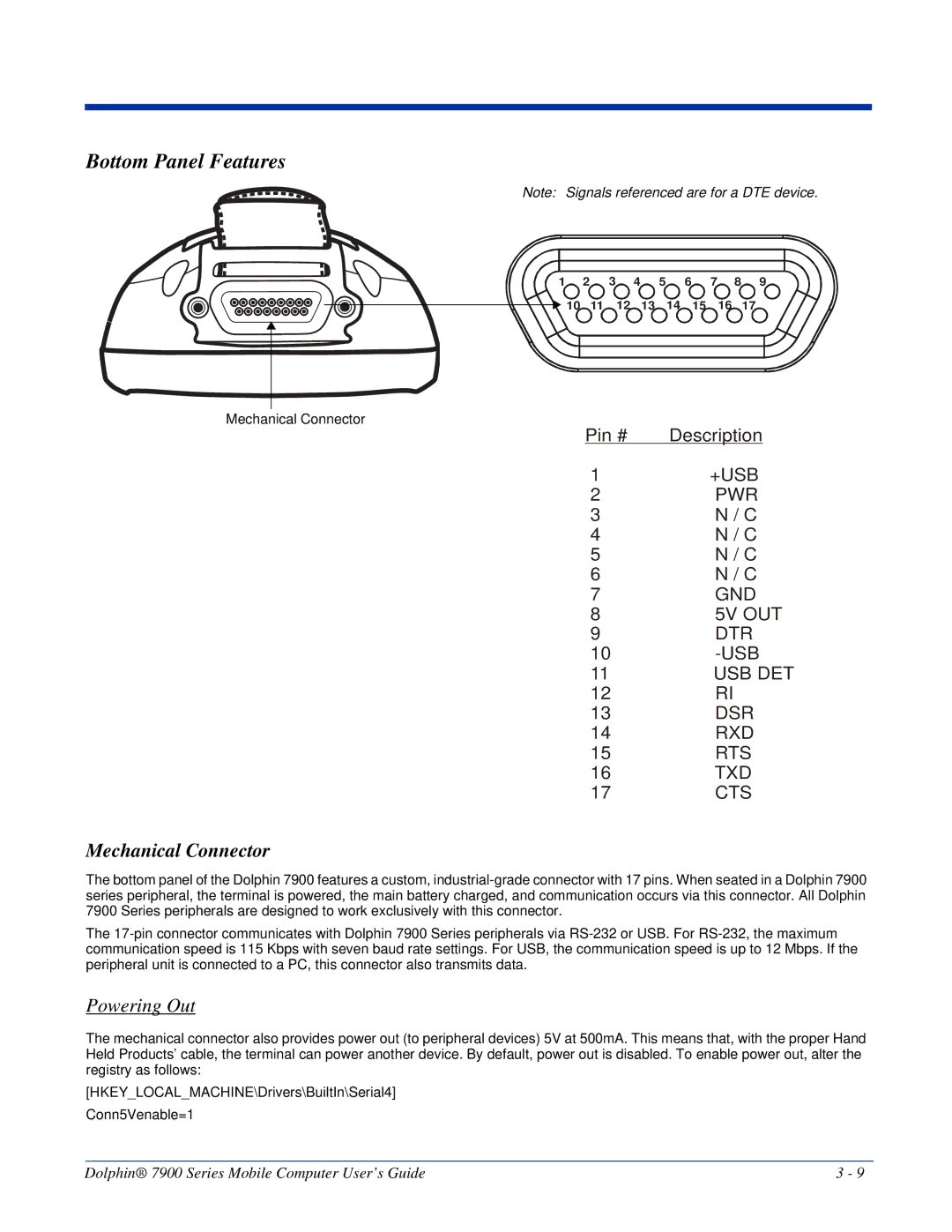
Bottom Panel Features
Mechanical Connector
Powering Out
Battery Power
Main Battery Pack
Internal Backup Battery
Managing Battery Power
Default Low and Critical Battery Points
Setting Critical and Low Battery Points
Checking Battery Power
Guidelines for Battery Use and Disposal
Storing Batteries
Dolphin 7900 Technical Specifications
Li-Ion Battery Pack
Temperature Humidity
Resistance Power
Peripherals/Accessories
Using the Touch Screen
Using the Dolphin 7900 Terminal
Command Bar
Today Screen
Navigation Bar
Pop-Up Menus
Selecting Programs
Adjusting the Backlight
Software Communication Programs
Wireless Radios
Communication Options
IrDA Port
Radio Manager
Radio Driver Installation
Radio Options
Radio Combinations
Disabling Radios
Enabling Radios and Radio Combinations
Using the Block Recognizer
Using the Soft Input Panel SIP
Using the SIP Keyboard
Using the Letter Recognizer
Selecting Text
Input Panel Options
Input tab Word Completion tab Options tab
Writing on the Screen
Drawing on the Screen
To Select Writing
Status Icons
Notifications
Status Icon Meaning
Using Find
Using File Explorer
Finding and Organizing Information
Imageteam 4300 Smart Focus IT4300SF
Using the Image Engine
Image Engine Options
Imageteam 4300 Standard Range IT4300SR
Bar Code Symbologies Supported
OCR Codes
Postal Codes
Programmable Side Buttons
Activating the Engine
Demos
Decoding
Sample Bar Codes
Omni-Directional Scanning Position Options
IT4300SF/SR High-Vis Aiming Pattern
Uploading Images
Capturing Images
Taking an Image
High-Vis Aiming Pattern
Dolphin 7900 Series Mobile Computer User’s Guide
Using the Function Keys
Using the Keyboards
Press To …
Using the Navigation Keys
Space SP
Tab
Using the Modifier Keys
Key combination pressed
Blue Red
Alpha Mode
Caps Lock Key in Alpha Mode
Key Numeric Keyboard
Key Combination Function
Blue Key Combinations
Red Key Combinations
Key Character
Red + F10
Key Alpha Keyboard
NUM Lock Key
Caps Lock Functionality
NUM Key Combinations
Numeric Shift in Numeric Mode
Dolphin 7900 Series Mobile Computer User’s Guide
Settings
System
Connections
Personal Tab
Buttons
Additional Functions
Available Applications
Headset Type
Mic Volume
Headset Volume
Headset Control
Adding a Program to the Start Menu
Using System Settings
Using File Explorer
Tap Start Settings Personal tab Menus Start Menu tab
Using ActiveSync on the Desktop Computer
System Tab
About
Backlight
CPU Speed
Clock & Alarms
Certificates
ClearType Tuner
To Increase/Decrease RAM Memory
Main tab
Functions
Free
Storage Card tab
Total storage card
Memory Use
Find Link
Tab Battery Tab Wireless Tab This tab enables you to …
Power
Regional Settings
Tab Advanced Tab This tab enables you to …
Options below the tabs
To Remove Programs
Remove Programs
Alignment tab
Screen
Text Size Tab
ClearType Tab
Default Font Size Largest Font Size
Zero-Config Wi-Fi
Connections Tab
Server-Assigned IP Addresses
Task tab
Com Port Assignment Table
Opening the Connections Manager
Com Assignment Port
Tap Start Settings Connections tab Connections Task tab
Creating an External Modem Connection to an ISP
Enter a name for the connection, such as My Connection
Tap FInish
Advanced Settings
Port Settings Tab
General Tab
Connecting to Your ISP
TCP/IP Tab
Servers Tab
Establishing Exceptions for Work URLs
Setting up a Proxy Server Connection for Work Connections
Go to Start Settings Connections tab Connections
Creating an External Modem Connection to Your Work
Setting Up a VPN Connection for Work Connections
Dolphin 7900 Series Mobile Computer User’s Guide
Connecting to a VPN Server
Select Edit my VPN servers
Establishing Dialing Rules
Creating a Wireless Network Connection
Network Cards
Help on Connecting
Installing Additional Software
Communications
Synchronizing from Your Desktop Computer
Using ActiveSync
Exploring the Terminal from the Desktop Computer
Synchronizing from the Terminal
Adding Programs to the Terminal Using ActiveSync
If the File is an Installer
If the File is Not an Installer
Using Infrared
Verify That the IrDA Port is Enabled
IrDA Port Location on the Terminal
Receiving
Verify That Beam Settings Are Set to Receive
Sending and Receiving
Sending
Troubleshooting
Adding Programs Directly from the Internet
Using an ISP
Enabling the 802.11b Radio Driver
Wireless LAN Communications with 802.11b
Configuration Utilities
802.11b Wireless Security Supplement
Icon This icon means…
802.11b Settings
Tap Start Settings System tab 802.11b Settings
Icons
Status Tab
To 8192 from the drop-down list
Timeout ms
FieldDescription More Info
Ping
Config Tab
To Add an Active Ssid to the Preferred Profile Table
To Create a New Profile
Authentication Tab
Field Power Save Mode Slider Description
To Delete a Profile
Advanced Tab
About Tab
Field Preamble Mode Defaults Apply Description
Using the Status Icon
802.1X Supplicant Protocol Support
802.11b Wireless Security Supplement
Required Network Configuration Information Worksheets
Platforms Supported
MD5 Worksheet
Leap Worksheet
TLS/SmartCard Worksheet
Ttls Worksheet
Peap Worksheet
Opening the Client
Icon Indicators
Menu Item Tapping this item… Close
Main Screen
Port Status Icon
Client Menu
View Menu
Help Menu
Status Bar
Event Log
Port Menu
Configuring the Client
Configuration Screens
Port Menu Options Enable and Disable
Client Configuration Area
Accessing the Client Configuration Area
On this tab You…
User Tab
Tunneled authentication area
Identity Password Protocol
Field Use certificate Description
System Tab
Server Tab
Port Settings Area
Scan Move to Configured
Configured Networks section
Default Down Add Remove
Field Properties Protocol Tab Description
Adding a Wireless Network Configuration
WEP Mgmt Tab
WPA Settings Tab
Field WPA Mode PSK pass-phrase Description
Logging
About CertAdd
Installing Certificates with CertAdd
Installing Certificates with CertAdd
Certificate Requirements
Issue Possible Causes and Solutions
Advice and Workarounds
Select Peer-to-Peer Group ad hoc mode and Do active scan
Key to authenticate with AP
How 802.1X Works
Typical Message Exchange Using MD5 or TLS
Typical Message Exchange Using Ttls and Peap
Central User Administration
Benefits
Cisco Leap
Dynamic Session Specific Wireless Encryption Keys
Relative Merits of Authentication Protocols
Additional Advantages of Ttls and Peap
Security Feature
Differences Between Protocols
Challenge
Wireless PAN Communications with Bluetooth
Enabling the Bluetooth Radio Driver
Setting Up Your Bluetooth Card
Assign COM Ports
Discover Bluetooth Devices
Bond With Discovered Devices
Dolphin 7900 Series Mobile Computer User’s Guide
View Device Properties
Change Views
Set Up Your Favorite Device
Delete a Device From the Folder
Turn Radio Transmitter ON/OFF
Bluetooth ActiveSync
Dolphin 7900 Series Mobile Computer User’s Guide
Bluetooth LAN Access
Dolphin 7900 Series Mobile Computer User’s Guide
Obex
Exchange Business Cards
Send a Contact
Send a File
Dolphin 7900 Series Mobile Computer User’s Guide
Prepare for File Transfer
Browse Remote Device
Send/Receive Files or Folders
Create a Folder
Delete Files or Folders
Refresh Remote View
Connect/Disconnect
Receive Contact or File
Exit Bluetooth File Explorer
Enable File Sharing
Using the Dialer
Ericcson, Nokia 6210, NTT DoCoMo, Sony Phones
Get Connected Wizard
Dolphin 7900 Series Mobile Computer User’s Guide
Motorola Timeport 270C, Nokia 3650/6310/7650/8910/8910i
Dial Up to Your Network
Automatic Connections for Motorola Timeport 270C
Uncheck Wait for dial tone before dialing. Tap Finish
Automatic Connections for Nokia 6310/8910/8910i
Automatic Connections for Nokia 3650/7650
Wireless WAN Wwan Communications with GSM/GPRS
To Install a SIM Card
SIM Card
SIM Card Requirements
Status Icons and Bubble Options
Using uPhone
Accessing uPhone
Navigation Bar
Tap Call Answerphone to dial
Tap Power Phone Off to turn off
Using the Dialler
Displays in the Number/Name 2nd line
Making a Call
To Enter a Number
To Send a Call To a Dialed Number
Call Waiting
Receiving a Call
To Answer a Call
To Reject a Call
Making Conference Calls
Keyboard Combinations for Calls
Call Waiting
Placing a Current Call on Hold
Volume Control
Touchtones
Phonebook
Speed Dial
Tools Menu
Dial
Send SMS
Settings Menu
Speakerphone
Mic mute
Speakerphone
Audio Modes
Handset
Headset
WAV Files
Ringtone Configuration
Accessing Ringtone Configuration
Go to Start Settings Personal tab Ringtones icon or
Go to Start Programs uPhone Call Log or
Call Log
Call Log Options
Opening the Call Log
Exit Close the Call Log
Select this menu option To… Clear
Go to Start Programs uPhone SMS Manager, or
SMS Manager
Opening the SMS Manager
Folders
Sending an SMS Message
Inbox
Sent Folder
Outbox Folder
Tap this icon To…
Icons at the Top of the Message Screen
Clear Selection
Online Help
Edit Menu
Select All
Tab Windows
UPhone Configuration
Accessing
Go to Start Settings System tab uPhone icon
PIN protection
General Tab
Field Description Phone Number
Answerphone
Network Tab
Divert Tab
Not Diverted
To number
Bar Tab
Other Tab
Messaging Tab
To Select the Pre-Configured Gprs Settings
Gprs Settings
Gprs Connection
To Add a Gprs Setting
Dolphin 7900 Series Mobile Computer User’s Guide
Applications
Calendar
Creating an Appointment
Using the Summary Screen
Contacts
Creating Meeting Requests
Scheduling a Meeting
Searching for Contacts
Creating a Contact
Using the Summary Screen
Creating a Task
Tasks
Using the Summary Screen
Synchronizing E-mail Messages
Connecting Directly to an E-mail Server
Messaging
Creating a Note
Receiving Messages
Using the Message List
Managing E-mail Messages and Folders
Composing Messages
Accessing Pocket Internet Explorer
Pocket Internet Explorer
ActiveSync
Mobile Favorites Folder
Default View One Column View
Browse the Internet on Your Terminal
View Options
Using Mobile Favorites and Channels
Creating and Synchronizing Mobile Favorites
Click View, Toolbars, and then Customize
Using AvantGo Channels
Pocket Word
Tap the AvantGo Channels link
Creating a Word File
Using Pocket Word
Typing Mode
Drawing Mode
Pocket Excel
Tips for Working in Pocket Excel
Creating an Excel File
Windows Media Player for Pocket PC
Setting Up
MSN Messenger
Tap Start Programs MSN Messenger
Pictures
Tap Tools Options Account tab
To begin, tap Start Programs Pictures
Dolphin 7900 HomeBase
Convenient Storage
Capacity
Terminal Well
AUX Battery LED
Dolphin 7900 HomeBase Parts and Functions
Front Panel
USB Port
Auxiliary Battery Well
DC Power Jack
Back Panel
HomeBase Serial Connector
Powering the HomeBase
Charging the Main Battery
To Power a Terminal and Charge its Main Battery
Charging a Spare Battery in the Auxiliary Battery Well
Communications
Setting Up the HomeBase for USB Communication
To Install the HomeBase Using USB
Setting up the Terminal for ActiveSync Communications
Dolphin 7900 Series Mobile Computer User’s Guide
Setting up the HomeBase for RS-232 Communications
Connecting the Cables
RS-232 Pin Configuration
Communicating with the Dolphin 7900 Terminal
Mounting the HomeBase
Verifying Communication
Verifying Data Transfer
Wall Mounting
Desk Mounting
Dolphin 7900 Series Mobile Computer User’s Guide
Mobile Base holds one terminal
Dolphin 7900 Mobile Base
Spring Arm Assembly
Dolphin Mobile Base Hardware Overview
Latch
Orange Data is being sent at high data rates
Power Supply Connector
Bottom Panel
Comm LED Color Indicates that… Red
RS-232 Serial Communications Port
TXD RXD DSR GND DTR CTS RTS Volt OUT
Ball Joint
Mounting Bracket
Ball Joint Connector
Mounting the Dolphin Mobile Base
Turnscrew
To Mount the Dolphin Mobile Base
Powering the Dolphin Terminal
Setting Up the Mobile Base for Communications
Charging the Dolphin Terminal
Configuring the Terminal for ActiveSync Communications
Dolphin 7900 ChargeBase
Dolphin ChargeBase Parts and Functions
Terminal Wells
Charge LEDs
Supplying Power to the ChargeBase
Power Supply
Dock LED
Inserting and Removing Terminals
Charging Terminals in the ChargeBase
Mounting the Dolphin ChargeBase
Using the DIN Rail
Using the Mounting Brackets
Dolphin 7900 Series Mobile Computer User’s Guide
Charging Process
Dolphin 7900 QuadCharger
Dolphin QuadCharger Parts and Functions
Compatibility
Rear Panel
Charging Batteries in the QuadCharger
Supplying Power to the QuadCharger
Inserting and Removing Battery Packs
Recommendations for Storing Batteries
To Analyze a Battery
Using the Battery Analyzer
Mounting the QuadCharger
Problem Issue
Troubleshooting
Product Service and Repair
Online Product Service and Repair Assistance
Customer Support
Technical Assistance
Online Technical Assistance
North America/Canada
How to Extend Your Warranty
Limited Warranty
Dolphin 7900 Series Mobile Computer User’s Guide
Page
Hand Held Products, Inc