The Switch Console
The Switch Console
Connecting a Console to the Switch
| Remote Console Connection Using a Modem and a PC | |
| Terminal Emulator or Terminal | |
|
| |
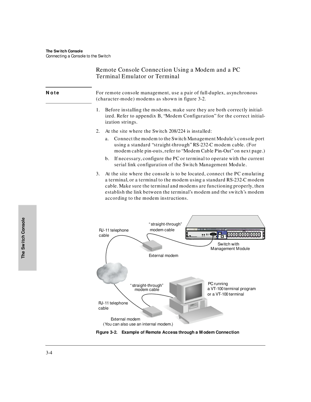
N o t e | For remote console management, use a pair of | |
| ||
| 1. Before installing the modems, make sure they are both correctly initial- | |
| ||
| ized. Refer to appendix B, “Modem Configuration” for the correct initial- | |
| ization strings. | |
| 2. At the site where the Switch 208/224 is installed: | |
| a. | Connect the modem to the Switch Management Module’s console port |
|
| using a standard |
|
| modem cable |
| b. | If necessary, configure the PC or terminal to operate with the current |
|
| serial link configuration of the Switch Management Module. |
3. At the site where the console is to be located, connect the PC emulating a terminal, or a terminal to the modem using a standard
| |
modem cable | |
cable |
|
| Switch with |
| Management Module |
| External modem |
PC running | ||
a | ||
modem cable | ||
| or a |
External modem
(You can also use an internal modem.)