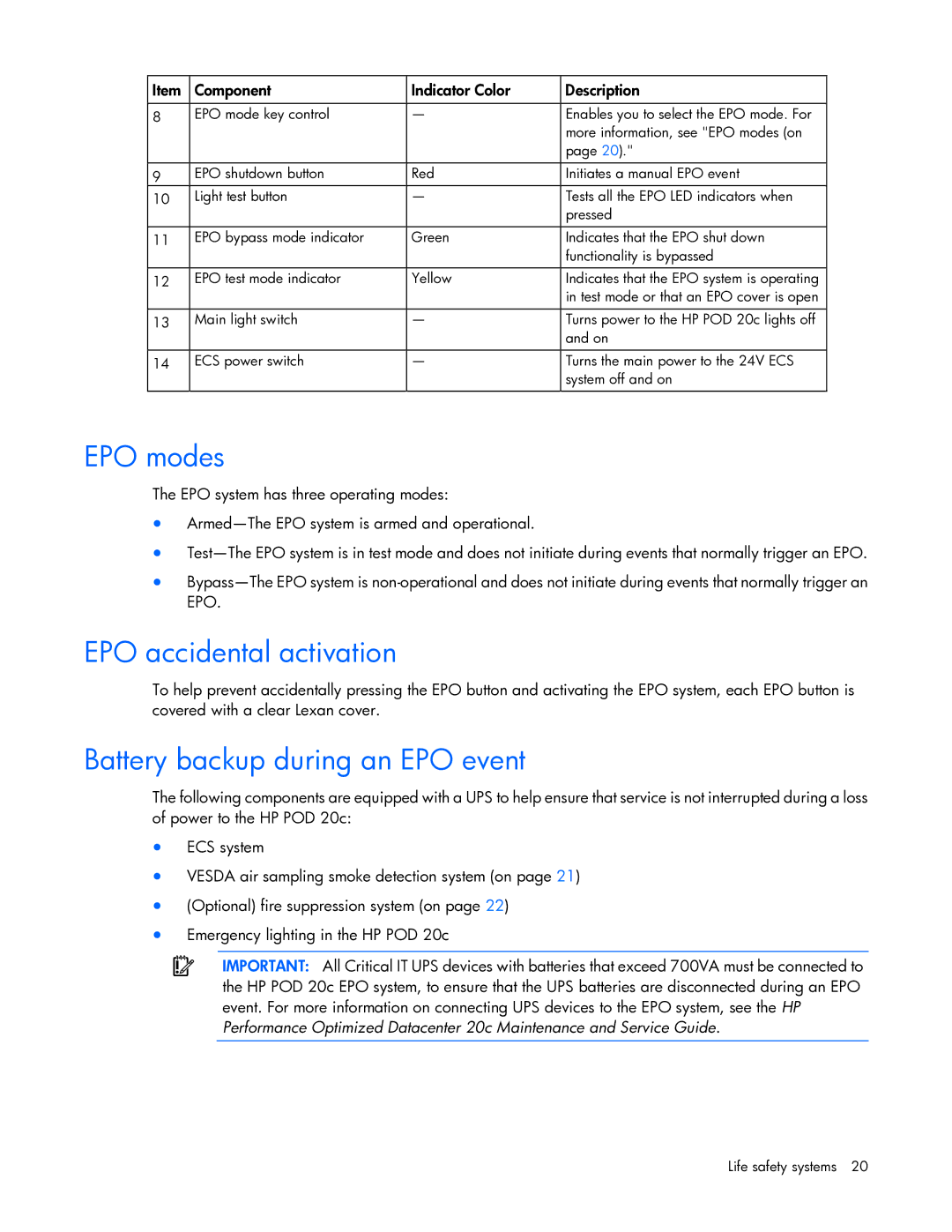
Item | Component | Indicator Color | Description |
|
|
|
|
8 | EPO mode key control | — | Enables you to select the EPO mode. For |
|
|
| more information, see "EPO modes (on |
|
|
| page 20)." |
|
|
|
|
9 | EPO shutdown button | Red | Initiates a manual EPO event |
10 | Light test button | — | Tests all the EPO LED indicators when |
|
|
| pressed |
|
|
|
|
11 | EPO bypass mode indicator | Green | Indicates that the EPO shut down |
|
|
| functionality is bypassed |
12 | EPO test mode indicator | Yellow | Indicates that the EPO system is operating |
|
|
| in test mode or that an EPO cover is open |
13 | Main light switch | — | Turns power to the HP POD 20c lights off |
|
|
| and on |
|
|
|
|
14 | ECS power switch | — | Turns the main power to the 24V ECS |
|
|
| system off and on |
|
|
|
|
EPO modes
The EPO system has three operating modes:
•
•
•
EPO accidental activation
To help prevent accidentally pressing the EPO button and activating the EPO system, each EPO button is covered with a clear Lexan cover.
Battery backup during an EPO event
The following components are equipped with a UPS to help ensure that service is not interrupted during a loss of power to the HP POD 20c:
•ECS system
•VESDA air sampling smoke detection system (on page 21)
•(Optional) fire suppression system (on page 22)
•Emergency lighting in the HP POD 20c
IMPORTANT: All Critical IT UPS devices with batteries that exceed 700VA must be connected to the HP POD 20c EPO system, to ensure that the UPS batteries are disconnected during an EPO event. For more information on connecting UPS devices to the EPO system, see the HP Performance Optimized Datacenter 20c Maintenance and Service Guide.
Life safety systems 20