Ascii Programmer’s Reference Manual
Page
Thermal Label Printers
USA
Trademarks and Service Marks
Page
Table of Contents
Series XQ Printer Protocol
Table of Contents
Serial Matrix Printer Protocol
IBM Proprinter III XL Printer Protocol
123
Epson FX-1050 Printer Protocol
171
FIM
EAN
UCC/EAN-128
Graphics
Ptrsetup Option
About This Manual
Overview
Introduction
Glossary
IBM PC
Software Features
OCR-A OCR-B
Printer Configuration
Printer Configuration
Introduction
Series Printer Protocol
CR = CR
Series Default Values and States
Series Default Settings Characteristic
Ascii USA
Page
Hex 01 Dec 1
Configuring the P-Series Emulation with Control Codes
Format for Control Code Descriptions
Special Function Control Code-Control Code Header
Command Line Error Messages Explanation
Command Line
Attribute Set and Reset Codes
Command Line
Print Attributes
Control Code Reference Index
Paper Motion
Format
Graphics
Control Code Reference Index
Other Functions
Ascii Code BEL Hex Code Dec Code
Backspace
Bell
Ascii Code BS Hex Code Dec Code
Bold Print
Bold Print Reset
Ascii Code CR Hex Code 0D Dec Code
Carriage Return
CR = CR+LF
Multinational Ecma Latin DEC Multinational
Character Set Select
Character Set Select
Hex Code Sfcc 6C xyz Dec Code Sfcc 108 xyz
IBM PC
Ascii Code Sfcc Hex Code
Characters 80-9F Printable Symbols
Characters 80-9F Control Codes
Characters 80-9F Control Codes
Ascii Code Sfcc OSETn
Character Set Select ECMA-94 Latin 1 Extended
Character Set Select International Languages
Elongated Double High Print One Line Only
Elongated Double High Print, Set/Reset
Elongated Double High Print, Set/Reset
Ascii Code Sfcc w n Hex Code
Emulation Reset
Emphasized Print Reset
Emphasized Print
Ascii Code Sfcc k Hex Code
Expanded Double Wide Print
Expanded Double Wide Print One Line Only
Expanded Double Wide Print
Sfcc 0F Sfcc 6F
Extended Character Set Cancel Primary Character Set Select
Extended Character Set
Sfcc 0E Sfcc 6E
Ascii Code FF Hex Code 0C Dec Code
Form Feed
Forms Length Set Inches
Form Feed
Ascii Code Sfcc v n1 n2 n3 n4
Forms Length Set Lines
Form Margins, Set
Ascii Code Sfcc LINESn
Line Feed
Line Feed
Ascii Code LF Hex Code 0A Dec Code
Line Spacing 1/6 Inch 6 lpi
Ascii Code ACK
Line Spacing 1/8 Inch 8 lpi
Line Spacing 8 or 10.3 lpi One Line Only
Line Spacing 1/8 Inch 8 lpi
Line Spacing 7/72 Inch
Line Spacing n/72 Inch
Line Spacing n/72 Inch
Ascii Code Sfcc a n Hex Code
Ascii Code Sfcc n Hex Code
Line Spacing n/216 Inch
Overscoring
Ascii Code Sfcc 3 n Hex Code
Ascii Code EOT
Plot, Even Dot P-Series High Density Graphics
Plot, Odd Dot P-Series Normal Density Graphics
Plot, Even Dot P-Series High Density Graphics
Ascii Code Sfcc X mn
Print Mode/Pitch Selection
OCR-A
Print Mode/Pitch Selection Print Mode and Pitch Sfcc PMODEn
Print Mode and Pitch Sfcc nq
Print Mode and Pitch
OCR-A OCR-B
Superscript/Subscript Printing
Superscript/Subscript Printing Reset
Underline
Super-Set Commands
Ascii Code Sfcc
Ascii Code VT Hex Code 0B Dec Code
VFU Commands P-Series
VFU Commands P-Series
Vertical Tab
Configuring the P-Series Emulation with Control Codes
Series XQ Printer Protocol
Series XQ Default Values and States
Page
Configuring the XQ Emulation with Control Codes
Configuring the XQ Emulation with Control Codes
NUL Code
Edit Mode
Edit Mode
CR Edit Mode Example Enter in Print Buffer Printed Result
Control Code Index
Ascii Code SI Hex Code Dec Code Purpose
Alternate Character Set Deselect Shift
Alternate Character Set Select Shift Out
Alternate Character Set Deselect Shift
Carriage Return
ETX
Compressed Print
Compressed Print
Ascii Code SOH
Delete Example Enter in Print Buffer Printed Result
Delete
Electronic Vertical Format Unit Evfu
Ascii Code DEL Hex Code 7F Dec Code
Elongated Characters Double High Print
Elongated Characters Double High Print
Ascii Code BS Hex Code Dec Code Purpose
Ascii Code ACK Hex Code Dec Code Purpose
Line Spacing 8 or 10.3 lpi
Plot, Even Dot P-Series XQ High Density Graphics
Plot, Even Dot P-Series XQ High Density Graphics
Ascii Code EOT Hex Code Dec Code
Ascii Code STX
Plot, Odd Dot P-Series XQ Normal Density Graphics
Select Letter Gothic DP
Ascii Code ENQ Hex Code Dec Code
Hex Code 5F Dec Code
Space
Space
Ascii Code SP Hex Code Dec Code
Vertical Tab
Serial Matrix Printer Protocol
Serial Matrix Default Settings Characteristic
Serial Matrix Default Values and States
LF = LF
LPI
CPI
Escape Control Code Header
Configuring the Serial Matrix Emulation with Control Codes
Ascii ESC G Hex 1B Dec 27
Control Code Index
DC1
ESC @
DC3
Bell
Bit Image Mode, Single Density
Ascii Code ESC K n1 n2 Hex Code
Ascii Code ESC Y n1 n2 Hex Code
Bit Image Mode, Double Density
Bit Image Mode, Double Density Double Speed
Ascii Code ESC L n1 n2 Hex Code
Ascii Code ESC Z n1 n2 Hex Code
Bit Image Mode, Quadruple Density
Bold Print Set
Bit Image Mode, Quadruple Density
Ascii Code ESC H Hex Code Dec Code Purpose
Cancel
Ascii Code can Hex Code Dec Code
Carriage Return
Character Pitch 10 cpi
Ascii Code ESC P Hex Code Dec Code Purpose
Character Set
Character Pitch 12 cpi
Ascii Code ESC M
Dec Code Purpose
IBM PC
Ascii Code ESC Hex Code Dec Code Purpose
Ascii Code ESC u Hex Code Dec Code Purpose
Characters 80-9F Printable Symbols
Ascii Code ESC R n Hex Code
Ascii Code SI
Condensed Print Reset
Condensed Print
Condensed Print
Unexpected print format may result
Ascii Code ESC E Hex Code Dec Code Purpose
Ascii Code ESC w n Hex Code
Ascii Code ESC @ Hex Code Dec Code Purpose
Ascii Code ESC F Hex Code Dec Code Purpose
Ascii Code SO
Through FF using codes hex 20 through hex 7F
Ascii Code ESC C NUL n Hex Code
Ascii Code ESC v n1 n2 n3 n4
Ascii Code ESC C n Hex Code
Ascii Code HT Hex Code Dec Code
Horizontal Tab
Horizontal Tab Set
Horizontal Tab
Ascii Code ESC J n Hex Code
Line Feed n/216 Inch One Line Only
Line Spacing 1/6 Inch
Line Spacing 1/6 Inch
Ascii Code ESC
Ascii Code ESC a n Hex Code
Ascii Code ESC 3 n Hex Code
Line Spacing n/216 Inch
Ascii Code ESC n Hex Code
Ascii Code ESC X mn
Print Mode and Pitch ESCnq
NLQ OCR-A OCR-B NLQ2
Configuring the Serial Matrix Emulation with Control Codes
Printer Select
Printer Deselect
Skip-Over Perforation
Ascii Code ESC S n Hex Code
Skip-Over Perforation Cancel
Super-Set Commands
Vertical Tab
Vertical Tab, Set/Clear
Vertical Tab, Set/Clear
112
IBM Proprinter III XL Printer Protocol
Proprinter III XL Emulation Default Settings
CPI
Escape Control Code Header
DC4
DC2
ESC K n1 NUL n2 n3 n4 n5
Bell
Bit Image Mode, Double Density
Bit Image Mode, Double Density Double Speed
Bit Image Mode, Quadruple Density
Bold Print Set
Bold Print Cancel
Bottom Margin, Set
Bottom Margin Cancel
Ascii Code ESC 5 n Hex Code
Carriage Return, Set
Control codes. Cancels Character Set Select activated by ESC
ESC DC
Ascii Code DC2
Ascii Code ESC Q Hex Code
Deselect Printer
Control code or DC4
Ascii Code DC4
Expanded Double Wide Print Reset 1 Line
ESC DC4
Forms length is defined in inches therefore, subsequent line
Forms length set becomes the current forms length. Forms
Ascii Code ESC D n1 n2...nk NUL
Horizontal Tab Set/Reset
Horizontal Tab Set/Reset
Horizontal/Vertical Tabs Clear
One byte follows n2
Initialize Parameters
N1 Values
Function
N5 Values
Initialize Parameters
N4 Values
Function OFF
If the emulation is configured for LF equals newline
Line Spacing 1/6 Inch 6 lpi
Line Spacing 7/72 Inch 10.3 lpi
Commands following an ESC 2 sequence* are at n/72-inch line
Ascii Code ESC X n1 n2 Hex Code
Margins, Left/Right, Set
Ascii Code ESC \ n1 n2 Hex Code
Print Control Codes
Print One Control Code
Overscoring
N2 Hex Function
Select Attributes
Select Attributes n1 Values
Select Attributes n2 Values
Ascii Code ESC I n Hex Code
Select Font Print Mode
Select Font Print Mode
Select Font Print Mode Hex
Ascii Code ESC P n Hex Code
Select Proportional Spacing
Top-of-Form
Superscript/Subscript Printing Reset
Ascii Code ESC U n Hex Code
Unidirectional Printing
Vertical Tab Set/Clear
Vertical Tab Set/Clear
148
Epson FX-1050 Printer Protocol
Epson FX-1050 Default Values and States
CPI
Epson Emulation Exceptions and Differences
Epson Character Sets
Epson Character Sets
Epson Character Set
Escape Sequences
Configuring the Epson FX-1050 Emulation with Control Codes
Hex 1B Dec 27
Set and Reset Codes
Set and Reset Codes
Print Modes Supported for Character Sets
Character Set Print Mode Support Courier Letter Gothic
OCR-A / OCR-B
Horizontal Motion
Vertical Motion and Print Execution
Data Manipulation
Emphasis
Print Quality Control
Character Set Manipulation
Backspace
Ascii Code BEL Hex Code Dec Code Purpose
Cancel Line
OCR B
Character Pitch 15 cpi
Character Pitch 10 cpi
Ascii Code ESC M Hex Code
Epson International Character Sets
Clear Bit 7 of Incoming Data Bytes to
Clear Bit 7 of Incoming Data Bytes to
Ascii Code ESC = Hex Code
Ascii Code ESC EM n Hex Code
Cut-Sheet / Paper Feed Control
Define a Download Character
Delete Character
Double High Print, Set/Reset
Double High Print, Set/Reset
Double Strike
Double Wide Print
Double Strike, Cancel
Ascii Code DC4 Hex Code Dec Code
Double Wide Print 1 Line, Cancel
Double Wide Print 1 Line
Double Wide Print 1 Line
Emphasized Print, Cancel
Enable Printing Hex Codes 00-1F and 80-9F
Enable Printing Hex Codes 00-1F and 80-9F
KEY
Graphics, Standard Density
Graphics, Double Density
Graphics, Double Density Double Speed
Graphics, Double Density Double Speed
Half Speed Mode, On/Off
Graphics, Quadruple Density
Horizontal Tab Set/Release
Horizontal Tab Execute
Horizontal Tab Execute
Initialize Printer
Italic Printing, Cancel
Italic Printing
Line Feed n/216 Inch
2 is Ascii character 2, not hex
Line Spacing 7/72 Inch
Make Hex 80-9F Printable
Make Hex 80-9F Control Codes
Make Hex 80-9F Printable Epson Printable Codes Hex 80-9F
KEY
Master Print Select Bit Values Bit No Bit =
Paper Out Detection, Enable
Master Print Select
Ascii Code ESC ! n Hex Code
Ascii Code ESC # Hex Code Dec Code Purpose
Paper Out Detection, Disable
Paper Out Detection, Disable
Pass Bit 7 from Host
Dec Code 27 58 0 n
Reassign Graphics Mode
Remove Downloaded Characters
Ascii Code ESC ? s m Hex Code
Select Graphics Mode
Select Graphics Mode
Ascii Code ESC t n Hex Code
Select 9-Pin Graphics Mode
Select Italic Character Set
Select Print Quality
Select Vertical Tab Channel
Select/Deselect Proportional Spacing
Select Serif or Sans Serif Font
Select User-Defined Font
Set Bit 7 of Incoming Data Bytes to
Set Absolute Horizontal Print Position in 1/60 Inch
Set Intercharacter Spacing in n/120 Inch
Ascii Code ESC l n Hex Code
Set Margin, Left
Set Margin, Right
Set Margin, Left
Set Forms Length in Inches
Set Forms Length by Lines
Set Vertical Tabs in Channels
Set Relative Horizontal Print Position in n/120 Inch
Set Relative Horizontal Print Position in n/120 Inch
Skip Over Perforation
Skip Over Perforation, Cancel
Ascii Code ESC O Hex Code
Ascii Code ESC T Hex Code Dec Code Purpose
Superscript and Subscript Printing, Cancel
Superscript and Subscript Printing
Superscript and Subscript Printing
Unidirectional Printing, 1 Line
Unidirectional Printing, Set/Reset
Vertical Tab, Execute
Vertical Tab, Execute
196
Ascii Value Hex Value
Super-Set Control Codes Protocol
Sfcc 7C 7D 3B
Ascii Code Sscc R n Hex Code
Character Set Selection
Epson FX Character Sets
199
MS DOS CP720
Super-Set Commands Proprinter XL Character Sets
Font Selection
Character Spacing n/240 Inch
Character Spacing n/240 Inch
Font Size
N4 Value Symbol Sets Printer Protocol
TrueType Font Selection
TrueType Font Selection
Form Length and Width
Host Form Size
Horizontal Movements in Printer Resolution
Line Spacing n/288 Inch
PCX Data
Ascii Code Sscc L n Hex Code
Orientation Select
Orientation Select
Portrait
Print Engine Options
Ascii Code Sscc X n Hex Code
Ascii Code Sscc # -n
Ascii Code Sscc w n1 n2
Image Width
Ascii Code Sscc s n Hex Code
Ascii Code Sscc M n Hex Code
Media Handling
Value Ascii Meaning
Ascii Code Sscc p n1 n2
Ascii Code Sscc t n Hex Code
Paper Cut
Ascii Code Sscc E -n
Ascii Code Sscc V n m
Power Saver Time
Ascii Code Sscc ! n Hex Code
Purpose Reboots the printer
Ascii Code Sscc o n Hex Code
Ascii Code Sscc i + n
Ascii Code Sscc n Hex Code
Ascii Code Sscc N n Hex Code
Ascii Code Sscc v -n
Ascii Code Sscc J Hex Code
Printer Protocol Select
Software Page Eject
Ascii Code Sscc P n
UPC-E
Software Page Eject
MSI
UPC-A
Bar Code Type Codes Selects Bar
Bar Code Format
Y Coordinate Unit System
Bar Code Format Bar Code Type Codes Selects Bar
Selects Location
Printable Data Field
Bar Code Format
FCC Codes and Maximum Bar Code Lengths
Australian 4-State
Valid Data Maximum Length
Codabar
Codabar
Codabar Character Set Hex
Bar Codes Check Digit
Code 39 Structure
Code
NUL
Code 39 Character Set
Code 93 Data Field
Code 93 Character Set Hex
Code 128A Data Field
Bar Codes Readable Data
Code Code 128A Character Set Hex Character Hex
Code 128B Character Set Hex
FNC
Code Code 128C Character Set Hex
Code B
Code a
EAN
EAN
EAN
FIM
Start/Stop Code
Interleaved 2/5 and German I-2/5 Structure
Interleaved 2/5 I-2/5 and German I-2/5
Standard Data Fields Character Title Positions
Maxicode
Maxicode
Standard Data Field
UPS Shipping Data Fields Character Title Positions
UPS Shipping Data Field
MSI
Security Level
PostBar and Royal Mail
PostBar and Royal Mail
Postnet
Telepen
Telepen
UCC/EAN-128
UCC/EAN-128 Application Identifiers
Content Format
248
Quiet Zone
Modulo-103 Check Digit
UPC-A
UPC-E
Eleven-Digit Compression
Bar Codes
UPC Shipping
UPC Shipping
UPS 11 Structure
UPS
Graphics
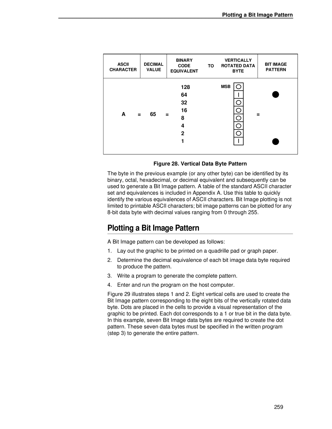
Vertical Data Byte Pattern
Binary Data Byte
Plotting a Bit Image Pattern
Plotting a Bit Image Pattern
128
Bit Image Pattern Plan
Bit Image Density
Bit Image Density
ESC CC n1 n2 Data
Bit Image Programming Format
Sample Single Density Bit Image Graphics
Bit Image Programming Format
Plot Density
Series Compatible Plot Mode Odd/Even Dot Plotting
Plot Data Byte Format
Plot Data Byte Format
Series Plot Data Byte Format
Plot Data Line Format
Plot Data Line Format
Double Density Plot
Odd Dot Plot Pattern Plan
Plotting the Data
To Exit the P-Series Plot Mode
To Exit the P-Series Plot Mode
Combining Graphics and Text
Vertical Page Formatting
VFU Load/Save/Clear
When the VFU is selected but not loaded
Channel Assignment
Start Load Code-Hex 1E or 6E
Start Load Code-Hex 1E or 6E
End Load Code-Hex 1F or 6F
Using the Evfu
Series Evfu
Data Bits Hex Dec Code Channel
Using the Evfu Series Evfu Codes PI Line Enabled
SOH STX ETX EOT ENQ ACK BEL
Clearing the Evfu Memory
Series Evfu Series Evfu Codes PI Line Disabled or Not Used
DC1 DC2 DC3 DC4 NAK SYN ETB Can SUB ESC
Relative Line Slewing
Relative Line Slewing
Data Bits Hex Dec Code Lines Slewed
Serial Matrix VFU Series Evfu Line Slewing
DLE DC1 DC2 DC3 DC4 NAK SYN ETB Can SUB ESC
Form Data Form Line Vertical Tabs Number
Executing Vertical Tabs
Vertical Tab Positions
Executing Vertical Tabs
Serial Matrix VFU
Standard Ascii Character Set
Appendix a
Ptrsetup Option
Appendix B The Ptrsetup Commands
Commands
Ptrsetup Commands Sub-Command Parameter Description
Upload
Config Delete
Reset
LP Mode
Minsize
Almenable
Fileio Runfile
Maxsize
Mediahandling
Engine Imageshfth
Imageshftv
Length
Operation of the Fileio Command
Series Plot Byte Definition
Dot
Byte
Ascii
Glossary
Appendix D
Always the Ascii ESC character. See also command
Appendix D
Sentence is set in italics
OCR
Novram
ROM
RAM
Special Function Control Character. The first character
Page
300
Index
Ptrsetup
Config
Page
Page
Evfu
Page
Oset
Postnet
Page
Page
Page
312
Readers’ Comments We’d Like to Hear from You
Business Reply Mail
Page
176977-001