Installation, User’s and Maintenance Guide
Page
Installation, User’s and Maintenance Guide
Sixth Edition November Copyright IBM Corporation
Contents
Installing the storage subsystem
Cabling the storage subsystem
Operating the storage subsystem
Hardware maintenance
Replacing components
Appendix B. Rack mounting template
Appendix D. Additional DS4000 documentation
Contents
Page
Figures
Page
Figures
Page
Tables
Xiii
Page
Safety
Statement
To Connect To Disconnect
Use safe practices when lifting
Page
Safety
Cable Warning
How this document is organized
About this document
Who should read this document
DS4000 Storage Subsystem installation tasks General overview
Installation task Where to find information or procedures
DS4000 EXP100 Storage Expansion Unit Installation, User’s
DS4000 Storage Manager Installation and Host Guide for
Copy Services premium features
FC/SATA Intermix premium feature
Storage Partitioning and general premium features
Information
Before you call
Getting information, help, and service
Using the documentation
Finding DS4000 readme files
Web sites
Software service and support
Hardware service and support
Mail
How to send your comments
Fire suppression systems
Page
Introduction
Overview
Models
Inventory checklist
Operating system support
Fibre channel defined
Sata defined
Software and documentation
Product updates and support notifications
Best practices guidelines
Storage subsystem components
Enhanced Disk Drive Modules E-DDMs
DS4700 Express hot-swap drive bays
Connectors, switch, and enclosure ID
Controllers
Introduction
Number Description
Setting up IP addresses for DS4000 storage controllers
Subnet Mask
AC power supply and fan units
Power supply and fan unit a
DC power supply and fan units
Power supply and fan unit and airflow
DC power supply and fan unit
DC power connector A21
Battery units
Battery unit Description of Figure
SFP modules
Telco bezel
Software and hardware compatibility and upgrades
Bezel
Software and firmware support code upgrades
Determining firmware levels
Specifications
Dimensions
Area requirements
To obtain the controller firmware version
Weight
Shipping dimensions
Unit Weight
Height Width Depth 45.7 cm 18.0 62.6 cm 24.5 80.7 cm 31.75
Condition Parameter Requirement
Environmental requirements and specifications
Temperature and humidity
Altitude
Airflow and heat dissipation
Environment
Altitude
Acoustic noise
Electrical requirements
Shock and vibration requirements
Low Range High Range
Heat output, airflow, and cooling
T42 racks
Page
Installing the storage subsystem
Installation overview
Serial number Machine type Model number
Handling static-sensitive devices
Preparing for installation
Tools and hardware required
Preparing the site
Installing the support rails
Preparing the rack cabinet
DS4700
Rear
Installing the storage subsystem
Installing the DS4700 Express
Removing the CRUs
Removing a controller
Removing an ac power supply and fan unit
Removing and replacing a controller
Removing a dc power supply and fan unit
Removing a power supply and fan unit
Page
Removing a dc power supply and fan unit
Removing an E-DDM
Removing a E-DDM CRU
Installing the DS4700 Express
Replacing the components
Replacing a controller
Replacing an ac power supply and fan unit
Replacing a dc power supply and fan unit
Replacing a power supply and fan unit
Installing the storage subsystem
Replacing a dc power supply and fan unit
Replacing an E-DDM
Installing a Telco bezel
Replacing an E-DDM
Installing a Telco bezel
Enclosure ID settings
Cabling the storage subsystem
Fibre-channel loop and ID settings
Working with SFPs and fiber-optic cables
Handling fibre-optic cables
Installing SFP modules
Cabling the storage subsystem
Removing SFP modules
SFP module and protective cap
Using LC-LC fibre-channel cables
Unlocking the SFP module latch plastic variety
Connecting an LC-LC cable to an SFP module
LC-LC fibre-channel cable
Removing fiber-optic cable protective caps
Using LC-SC fibre-channel cable adapters
Removing an LC-LC fibre-channel cable
Connecting an LC-SC cable adapter to a device
LC-SC fibre-channel cable adapter
Removing an LC-LC cable from an LC-SC cable adapter
Removing the LC-SC cable adapter protective caps
Replace the protective caps on the cable ends
Redundant drive channel pair
DS4700
DS4700 Express Storage Subsystem drive cabling topologies
Controller a Controller B
One DS4700 Express and one storage expansion enclosure
One DS4700 Express and two storage expansion enclosures
Controller B Left ESM Right ESM
One DS4700 Express and three storage expansion enclosures
One DS4700 Express and four storage expansion enclosures
Left ESM Right ESM
Ds470058
Controller B Left ESM Right ESM
Page
DS4000 storage subsystem. shows the location of the ports
Storage expansion enclosures ESM ports
DS4700 EXP100
Ds470052
Ds470053
Ds470054
DS4700 EXP100
Ds470052
Ds470053
Ds470054
DS4000 Storage Subsystem
Ds470038
Ds470055
Ds470056
Ds470057
Page
DS4700 Express Storage Subsystem
DS4000 Storage Subsystem
DS4000 storage expansion enclosure ID settings
Storage expansion enclosure settings
Fibre channel loop and ID settings
Enclosure
Enclosure ID of storage expansion enclosures in a
Redundant drive channel
Total number
Connecting secondary interface cables
Ethernet and serial port locations on DS4700 Express model
Configuring the storage subsystem
Storage subsystem management methods
Host-agent in-band management method
Direct out-of-band management method
Cabling the storage subsystem
Connecting hosts to the DS4700 Express
Direct out-of-band managed storage subsystems
Controller a Controller B Host Ports
Cabling diagram for two redundant host connections
Fibre channel host loop configurations
Fibre channel connections
Redundant host and drive loops
Example of a single SAN fabric configuration
Installing the storage subsystem configuration
Example of two storage subsystems in a dual SAN environment
Cabling the ac power supply for ac models
Cabling the dc power supply for dc models
Single-level redundant dc cabling
Dual-level redundant dc cabling
On page 114 illustrates dual-level cabling
Ds470093
DC power source
Page
Operating the storage subsystem
Performing the DS4000 Health Check process
Web pages
Hardware responsibilities
Powering on the storage subsystem
Turning on the storage subsystem
Page
Installing the DS4000 Storage Manager client
Monitoring status through software
Operating the storage subsystem
Firmware updates
Troubleshooting the storage subsystem
Checking the LEDs
AC power supply and fan unit LEDs
DC power supply and fan unit LEDs
Normal Status Problem Status
Number
DC power supply and fan unit LEDs
Front LEDs
Battery unit LEDs
LED
Battery unit LEDs
Controller LEDs
10 11 12
Rear controller LEDs, controls, and connectors
Seven-segment numeric display LEDs
Definition
Value Controller State Description View
Powering off the storage subsystem
Storage Manager
Turning off the storage subsystem
Power-off overview
Performing an emergency shutdown
Restoring power after an unexpected shutdown
Recovering from an overheated power supply and fan unit
Operating the storage subsystem
Cache memory and cache battery
Cache memory
Cache Active LEDs Description of Figure
Subsystem cache battery
Shows the location of the Battery LEDs
Page
Service Action Allowed Status LED
Replacing components
Replacing a controller
Plastic tab Protective cap 10o SFP module
Removing a controller from the DS4700 Express
Installing a controller
Removing and replacing a bezel
Removing and replacing a bezel
DDM CRUs
Replacing a filter and filter retainer
Working with hot-swap E-DDMs
LED state Descriptions
Installing hot-swap E-DDMs
Hot-swap E-DDM LEDs
Replacing hot-swap E-DDMs
Replacing the E-DDMs one at a time
Replacing multiple E-DDMs
Replacing all the E-DDMs at the same time
Replacing all E-DDMs at the same time
Page
Replacing the E-DDMs one at a time
Page
Verifying the Link Rate setting
Data transfer rates for drive modules
Link rate LEDs
Replacing an ac power supply and fan unit
Statement
Statement
To Connect To Disconnect
Replacing a power supply and fan unit
Replacing a dc power supply and fan unit
Page
Replacing components
To Connect To Disconnect
Replacing components
Replacing a dc power supply and fan unit
Replacing a battery unit
Page
Replacing an SFP module
Bypass LED and Fault LED are off Go to step
Replacing a midplane
Replacing components
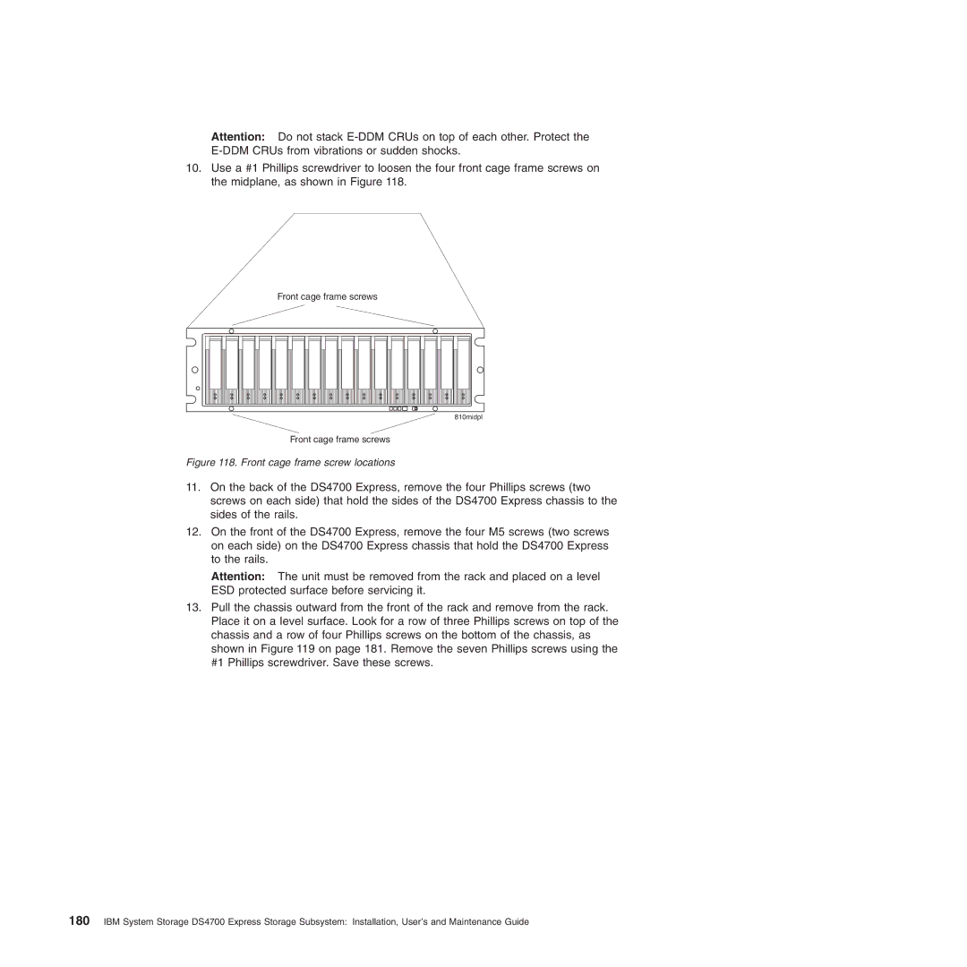
Front cage frame screw locations
Screws
Page
General checkout
Hardware maintenance
Solving problems
Symptom-to-FRU index
CRU
SFP
Replace the RAID controllers
Parts listing
Index DS4700 Express Storage Subsystem
FRU P/N
FRU P/N
Appendix A. Records
Identification numbers
Storage subsystem and controller information record
Sample information record
Installed device records
Appendix B. Rack mounting template
DS4700
Appendix B. Rack mounting template
Page
Appendix C. Power cords
199
IBM power cords
Appendix C. Power cords
Page
Appendix D. Additional DS4000 documentation
DS4000 Storage Manager Version 10 library
DS4800 Storage Subsystem library
DS4700 Storage Subsystem library
DS4500 Storage Subsystem library
DS4400 Storage Subsystem library
DS4300 Storage Subsystem library
DS4200 Express Storage Subsystem library
DS4100 Storage Subsystem library
DS4000 Storage Expansion Enclosure documents
Other DS4000 and DS4000-related documents
Action
Appendix E. Accessibility
Short cut
Short cut Action
Trademarks
215
Important notes
Contaminant Limits
Particulate contamination
Documentation format
Industry Canada Class a emission compliance statement
Avis de conformité à la réglementation dIndustrie Canada
Page
Korean Communications Commission KCC Class a Statement
Abstract Windowing Toolkit AWT. a Java graphical
Glossary
See also
Auto-volume transfer/auto-disk transfer AVT/ADT
Data striping. See striping
Fibre Channel Arbitrated Loop FC-AL. See
Automatic ESM firmware synchronization. When
Expansion port Eport. a port that connects
Host computer. See host
JRE. See Java Runtime Environment
ODM. See Object Data Manager
Peripheral component interconnect local bus PCI
RAM. See random-access memory
RAID set. See array
Simple Network Management Protocol SNMP.
SLport. See segmented loop port
Terminate and stay resident program TSR
Transmission Control Protocol/Internet Protocol
Page
Index
231
DDM
Fibre channel Connections
Link rate setting, verifying
SFP modules Described Replacing
Web sites
Page
Part Number 94Y8472