Manuals
/
Integra
/
Home Audio
/
Stereo Receiver
Integra
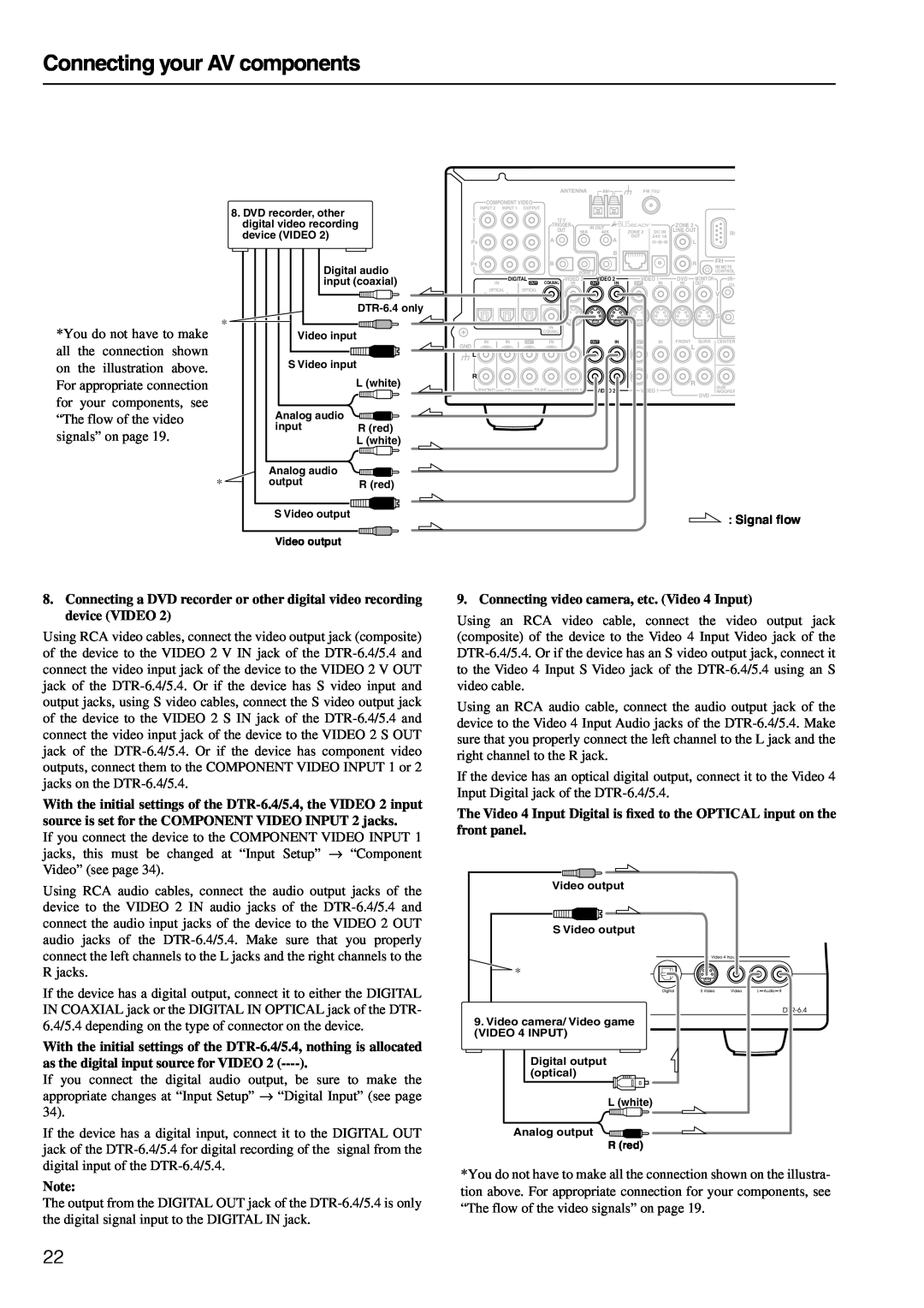
DTR-6.4/5.4 Connecting your AV components, Connecting video camera, etc. Video 4 Input
Models:
DTR-6.4/5.4
1
22
80
80
Download
80 pages
34.59 Kb
19
20
21
22
23
24
25
26
Troubleshooting
The flow of the video signals
TUNED indicator
Connecting speakers
Dimension
Erasing a preset radio station
Supplied accessories
Setup Menu
AV cables and connectors
the procedure
Page 22
Image 22
Page 21
Page 23
Page 22
Image 22
Page 21
Page 23
Contents
Setting up your DTR-6.4/5.430
Contents
Before using
Basic Settings
Important Safety Instructions
AVIS
4. Power
Precautions
Supplied accessories
For U.S. models Note to CATV system installer
Connecting your AV components
Contents
Before using
Connecting the remote zone Zone 2 speakers
Remote controller
Contents
Configuring your DTR-6.4/5.4Advanced Settings
Programming the commands of remote
DTR-5.4
Features
DTR-6.4
Amplifier Features
Installing the remote controller batteries
Before using this unit
Connecting the power cord
Using the remote controller
Index parts and facilities
DTR-6.4Front panel DTR-5.4Front panel
Index parts and facilities
AUTO indicator
Front panel display
TUNED indicator
MEMORY indicator
Rear panel
Index parts and facilities
MONITOR OUT VIDEO/S VIDEO
Remote controller
Index parts and facilities
IR IN/OUT
Send/Learn indicator
Index parts and facilities
For DTR-6.4only
About HomeTheater
Enjoying Home Theater
Center speaker
Cable forms
AV cables and connectors
Improper connection Inserted completely
Terminal shapes
Connecting speakers
Surround back speaker placement
Using the speaker cable labels
Connecting speakers
Connecting the speaker cables
Connecting a subwoofer
1. Connecting a compact disc player CD
Connecting your AV components
Connecting your audio components
2. Connecting a turntable PHONO DTR-6.4only
The flow of the video signals
Connecting your AV components
Connecting your video components
COMPONENT VIDEO INPUT/OUTPUT
Connecting your AV components
5. Connecting a DVD player DVD
Connecting your AV components
6. Connecting a video cassette recorder VIDEO
Connecting your AV components
9. Connecting video camera, etc. Video 4 Input
Connecting the power cords from other devices
Connecting your AV components
Connecting the included antennas
Connecting antennas
Connecting the AM antenna cable
Assembling the AM loop antenna
Connecting an AM outdoor antenna
Connecting antennas
Connecting an FM outdoor antenna
Directional linkage
When using the ZONE 2 LINE OUT terminals
Connecting the remote zone Zone 2 speakers
When using the ZONE 2 SPEAKERS terminals
When using the ZONE 2 PRE OUT terminals
From connecting block Mini plug cable
RS232
Connections for remote control
Miscellaneous Connections
A-BUS
Turning on the power
Connecting the power
Turning on the power from the remote controller
52,54
Setup Menu
53,55
Setup Menu
Buttons used for navigating through the menus
a. Surr/Zone
Hardware Config
b. Surr Back DTR-6.4only
Front speaker diameter
Speaker Configuration
Adjustable Crossover for Bass Management
crosscover frequency
a. Digital Input
Front speaker diameter
crosscover frequency
Notes
ENTER
Return Setup Tape
Return Setup
Changing the display
Basic operation
Enjoying music or videos with the DTR-6.4/5.4
Light button on the remote controller DTR-6.4only
Adjusting the brightness of the front display
Using the sleep time remote controller only
Listening with headphones
Enjoying music or videos with the DTR-6.4/5.4
Enjoying music or videos with the DTR-6.4/5.4
Switching the display
Temporarily changing the speaker output levels
Notes
Notes
Selecting the type of audio input signal
Enjoying music or videos with the DTR-6.4/5.4
Notes on DTS
Enjoying DVD multichannel audio playback
Using the tone control
Basic operation
Enjoying DVD multichannel audio playback
Changing the listening mode DTR-6.4only
Listening to Radio Broadcasts
Tuning into a radio station
Listening to a stereo radio station FM mode
Erasing a preset radio station
Presetting a radio station
Selecting a preset radio station
Listening to Radio Broadcasts
T-D Theater-Dimensional
Listening Modes
Listening Modes
Mono
Mono Movie
Listening Modes
• THX Surround EX
Enhance
Re-EQfunction for movies DTR-6.4only
Selecting a listening mode DTR-6.4
Listening Modes
Selecting a listening mode DTR-5.4
Listening Modes
•While playing back DTS sources
Fixing playback to specific surround mode
Listening Modes
•While playing back DTS sources THX Cinema
Enjoying music in the remote zone
Using the buttons
Adjusting the volume for the remote zone
Using the remote controller
Notes
Recording
Recording the input source Rec Out selector
Notes
Recording both the audio and video
Recording
Hint
Configuring the speakers DTR-6.4
Notes
Calibrating the speaker levels
Configuring the speakers DTR-6.4
Notes
Setup
Configuring the speakers DTR-5.4
Setup Return
Return
the procedure
Configuring the speakers DTR-5.4
Using the remote controller
Calibrating the speaker levels
Input Setup
d. Analog/PCM/D. F. 2ch source
Input Setup
Configuring the listening modes frequently you use
e. PCM fs 96kHz source
Switching the OSD display mode
Adjusting the headphones volume level
Setting the background color for OSD
Changing the volume level display setting
Bass
Audio Adjust
Treble
Double Bass
Audio Adjust
Pro Logic II Music Dimension Dimension
Late Night
Reverb Level
Settings available when you play monaural signal
Audio Adjust
Reverb Time
Overview
Using remote controller
Calling up a preset radio station
Controlling an Onkyo cassette tape deck
Using remote controller
Controlling an Integra/Onkyo DVD player
1. Press the CD Mode button
Controlling an Integra/Onkyo CD player
Using remote controller
Disc
Rec : Record
Controlling an Onkyo MD recorder
Using remote controller
1 to 9, 0, --/---: Numeric keys
Entering a pre-programmingcode
Learning a pre-programmingcode
Entering a pre-programmingcode
Pre-programmingcodes
SAT Mode Satellite Tuner Mode
Operating your programmed remote controller
DVD Mode DVD Player Mode
Cable Mode Cable Mode
TV Mode TV Mode
Operating your programmed remote controller
VCR Mode VCR Mode
0,1 to 9, +10: Numeric keys
Programming procedure
Notes
Erasing the programmed command from one button
Notes
Programming the macro
Using the macro function
What is the macro function?
Executing the macro
Notes
Using the macro function
Erasing a macro from the Macro 1 or 2 button
Notes
AMPLIFIER SECTION
Specifications DTR-6.4
REMOTE CONTROLLER
TUNER SECTION
AMPLIFIER SECTION
Specifications DTR-5.4
REMOTE CONTROLLER
TUNER SECTION
SPEAKERS
Troubleshooting guide
POWER
FM/AM TUNER
VIDEO and AUDIO
Troubleshooting guide
REMOTE CONTROLLER
OTHER
“Not available with headphones use”
If one of the messages shown below appears
Troubleshooting guide
“Not available with this signal”
Memo
Tel: 072-831-8111Fax:
Integra Division of ONKYO U.S.A. CORPORATION
Integra Division of ONKYO CORPORATION
Printed in Japan
Top
Page
Image
Contents