DTR-7.4
Important Safety Instructions
Precautions
Table of Contents
Table of Contents
Features
Supplied Accessories
Using the Remote Controller
Before Using the DTR-7.4
Installing the Batteries
Remote control sensor DTR-7.4 Standby indicator
Protective caps
Index Parts and Facilities
Front Panels
Protective caps
Index Parts and Facilities
Front Panel Display
Rear Panel
Antenna
Digital IN/OUT
PRE OUT 18, 25
Zone 2 OUT
Remote Controller
Amp Mode
Remote Controller
Connecting the Indoor FM Antenna
Connecting Antenna
Connecting the AM Loop Antenna
Attach the FM antenna, as shown
Connecting Antenna
Connecting an Outdoor FM Antenna
Connecting an Outdoor AM Antenna
How to use speakers
About HomeTheater
Enjoying Home Theater
Speaker Placement
Important Points Regarding Speaker Placement
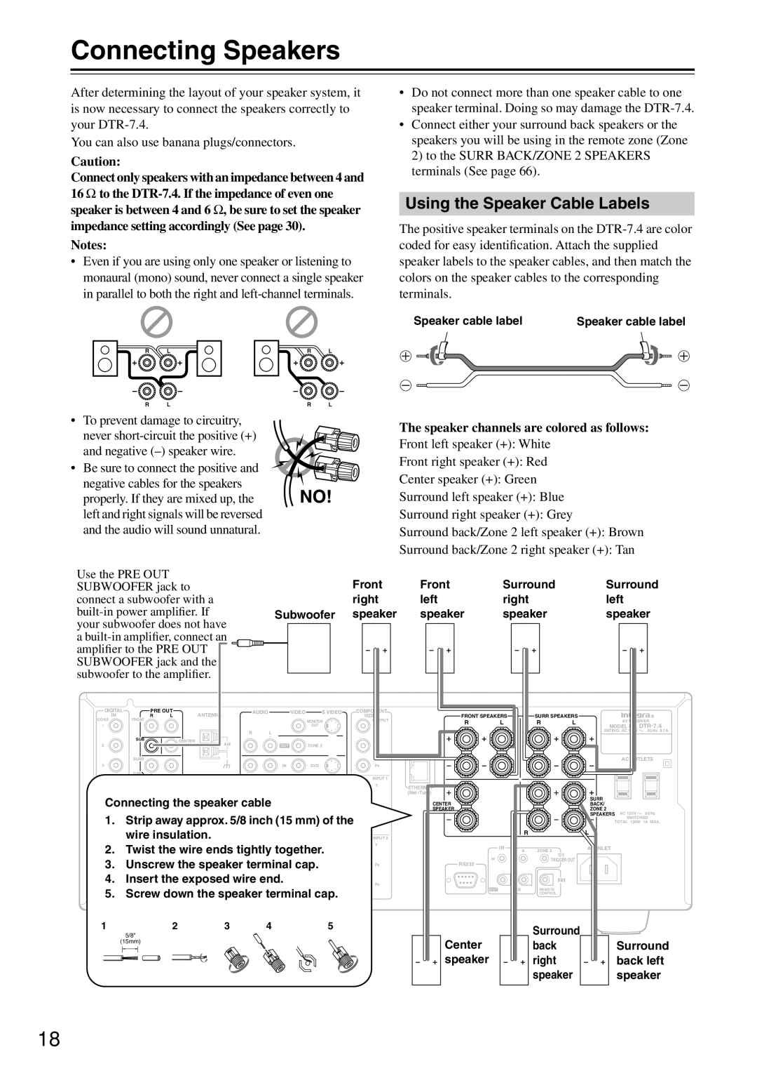
Connecting Speakers
Using the Speaker Cable Labels
Speaker channels are colored as follows
AV Cables and Connectors
flow of the video signals is as follows
Connecting to Audio/Video Equipment
Connecting a Television Monitor or Projector Monitor OUT
TV,PB projector Etc.PR
Connecting to Audio/Video Equipment
DVD player
Digital device DVD recorder
Satellite tuner, television, or settop box
Connecting a Turntable Phono
Connecting a Compact Disc Player CD
Connecting Video Camera, etc. Video 5 Input
Ground wire earth
Connecting the Power Cords from Other Devices
USA and Canadian models Australian model
Surround right
Connecting Auxiliary Power Amplifier
Surround back right speaker
Center speaker
Power on/ready function
Connecting -compatible AV Components
Connections for Remote Control
Power off function
Connecting the Supplied Power Cord
Connecting the Power
Turning on the Power
Turning on the Power from the Remote Controller
Menu
Setup Menu
Basic
Advanced
Setup Menu
ΜNavigating Through the Setup Menu
Display the main menu
Hardware Setup
Hardware Setup menu appears
Speaker Impedance Sub-menu
Selecting the Appropriate Setting for Your Connections
Remote Setup Sub-menu
Surr Back/Zone 2 Sub-menu
Speaker Setup
Changing the Remote Controller’s Control ID
TV Format Sub-menu
Speaker Config Sub-menu
Speaker Distance Sub-menu
Level Calibration Sub-menu
Use the and cursor buttons to select Left
Press the cursor button again
Configuring Input Settings Suitable for Your Connections
To Change the Display of the Input Source from Tape to MD
Configuring Input Settings Suitable for Your Connections
Input Setup
Digital Setup Sub-menu When NET AUDIO, FM, or
Initial settings for each input source
Digital Format
Video
Multichannel Setup Sub-menu When NET Audio
Video Setup Sub-menu
Component Video
DTR
Your
Basic Operation
Listening with headphones
Enjoying Music or Videos with the DTR-7.4
Temporarily turning off the sound
Enjoying Music or Videos with the DTR-7.4
Using the Sleep Timer remote controller only
Adjusting the brightness of the front display
Temporarily Changing the Speaker Output Levels
Dialog norm
Switching the display
DTR-7.4 or the remote controller
DTR-7.4Press the Display button on
Input source you want to set
Changing the audio mode
Adjusting the bass and treble
Press the scroll wheel and then
Using the Listening Modes
Listening Modes
Using the Listening Modes
Start playback on the device you
Selecting the Listening Mode
Select the input source
Selected for input
THX Changes the listening mode to the THX listening mode
Relationship between input source and listening mode
Listening to Radio Broadcasts
Tuning Into a Radio Station
Listening to a stereo radio station FM mode
Specifying Radio Stations by Frequency
Erasing a preset radio station
Presetting a Radio Station
Selecting a preset radio station
Listening to Radio Broadcasts
Recording a Source
Recording a Source
Labelling the Input Source Character Input
Input Setup Basic
Select 2. Input Setup and then
Input source you want to name
Input Setup Basic
Audio Adjust Basic
Adjusting the Bass and Treble Sound Tone Control
Audio Adjust Basic
Setting the Various Sound Effects Sound Effect
Input Setup and then press the Enter
Input Setup Advanced
Press the scroll wheel, and then press the Setup button
Press the Setup button to return to the main menu
Audio Adjust Advanced
Input Setup Advanced
Adjusting the Audio Delay Delay Sub-menu
Detailed Settings for Each Listening Mode
Audio Adjust Advanced
Setting the Low Frequency Effect Levels LFE Level
Mono Sub-menu
Theater-Dimensional Sub-menu
Surround Sub-menu
DTS-ES
Pro Logic II Music Dimension
Dolby Digital EX Dolby D
Pro Logic II Music Panorama
THX Sub-menu
Volume Setup Sub-menu
Preference Advanced
Switching the OSD Position
Adjusting the Headphone Volume Level Headphones Level
Setting the Background Color for OSD OSD Setup
Preference Advanced
Connecting to Devices with Analog Multichannel Output
Setup for Multichannel Output
Enjoying Analog Multichannel Audio Playback
Enjoying Analog Multichannel Audio Playback
Changing the listening mode
Using the tone control
Playing Analog Multichannel Audio
Using a Power Amp in Zone
Connecting Zone
Using a Receiver/Integrated Amp in Zone
Using Only Speakers in Zone
Performing the Settings for the Remote Zone Zone
Enjoying Music in the Remote Zone
Enjoying Music in the Remote Zone
From connecting block Mini plug cable DTR-7.4
If Remote Controller Signal Does not Reach Other Components
Setup Menu See
Output to the IR OUT terminal
Using the Remote Controller with Radio Frequency
Configuring the 12V Trigger Terminal
Using an External Device with 12V Trigger Terminal
Connecting to an External Device with 12V Trigger Terminal
Press the Input button, and then roll
Net-Tune Features
Features
Internet radio features
Enjoying Net Audio
Internet
Connecting the DTR-7.4 to Your Ethernet Network
Enjoying Net Audio
Internet radio Network Audio Server Modem To the WAN side
JKL
CH/Disc button
Mode button 80
Number/letter buttons
Play Button
Network Setup Menu
Proxy Setup Sub-menu
IP Address Sub-menu
Client Sub-menu
Input Setup Menu
MAC Address Sub-menu
Press the Input button,
Select Server
Playback OSD Display Sub-menu
Playback OSD Display
Enjoying Internet Radio
Presetting Internet radio stations
Choosing a preset Internet radio station
Erasing a preset Internet radio station
Turn on the DTR-7.4
Mode button is illuminated
Turn on the Network Audio Server
While either the Input button nor
Playing a music file at random
Selecting a track list
Use Buttons to select one From the menu
Playing a music file repeatedly
Operating Onkyo Products Using the Remote Controller
Operating Onkyo Products Using the Connection
DVD Mode
Operating Onkyo Products Using the Remote Controller
CD Mode
Previous/Next / buttons
FR/FF / buttons
Current track. The Next
MiniDisc Mode
Mode button Eject button
Select the next track
Tape Mode
Rewind/FF / buttons
Reverse Play button
Using the Remote Controller with Other Components
Entering a Remote Control Code
Remote Control Codes for an Onkyo DVD player
DVD DVD Player
Using the Remote Controller with Other Components
Remote Control Codes
SAT satellite receiver
JBL
Controlling a Satellite Receiver Controlling a VCR
Following buttons control the DTR-7.4
Controlling a TV Controlling a Cable Receiver
Standby TV CH +
TV VOL
Learning Commands from Another Remote Controller
Using Macros
Making Macros
Running Macros
Editing Remote Controller Modes
Adding New Remote Controller Modes
Naming Macros
Mode before which you want to
Type of mode you want to add,
Reordering the Remote Controller Modes
Deleting Remote Controller Modes
Resetting the Remote Controller
Assigning Remote Controller Modes
Troubleshooting Guide
Symptoms Causes Remedies
Troubleshooting Guide
AM and FM stations
101
If One of the Messages Shown Below Appears
Specifications
Amplifier Section
104