|
|
| Networking Silicon — 82555 |
|
|
|
|
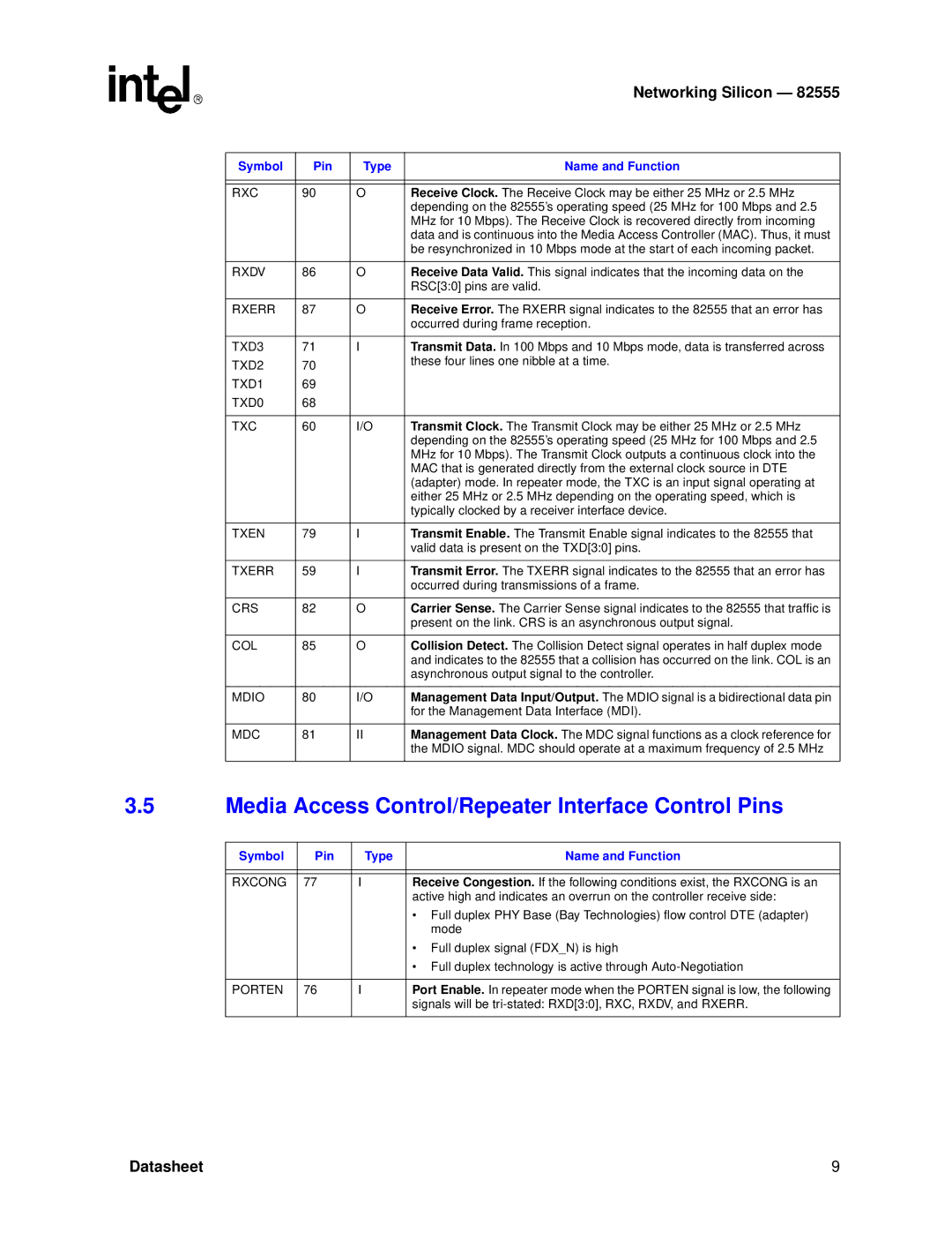
Symbol | Pin | Type | Name and Function |
|
|
|
|
|
|
|
|
RXC | 90 | O | Receive Clock. The Receive Clock may be either 25 MHz or 2.5 MHz |
|
|
| depending on the 82555’s operating speed (25 MHz for 100 Mbps and 2.5 |
|
|
| MHz for 10 Mbps). The Receive Clock is recovered directly from incoming |
|
|
| data and is continuous into the Media Access Controller (MAC). Thus, it must |
|
|
| be resynchronized in 10 Mbps mode at the start of each incoming packet. |
|
|
|
|
RXDV | 86 | O | Receive Data Valid. This signal indicates that the incoming data on the |
|
|
| RSC[3:0] pins are valid. |
|
|
|
|
RXERR | 87 | O | Receive Error. The RXERR signal indicates to the 82555 that an error has |
|
|
| occurred during frame reception. |
|
|
|
|
TXD3 | 71 | I | Transmit Data. In 100 Mbps and 10 Mbps mode, data is transferred across |
TXD2 | 70 |
| these four lines one nibble at a time. |
|
| ||
TXD1 | 69 |
|
|
TXD0 | 68 |
|
|
|
|
|
|
TXC | 60 | I/O | Transmit Clock. The Transmit Clock may be either 25 MHz or 2.5 MHz |
|
|
| depending on the 82555’s operating speed (25 MHz for 100 Mbps and 2.5 |
|
|
| MHz for 10 Mbps). The Transmit Clock outputs a continuous clock into the |
|
|
| MAC that is generated directly from the external clock source in DTE |
|
|
| (adapter) mode. In repeater mode, the TXC is an input signal operating at |
|
|
| either 25 MHz or 2.5 MHz depending on the operating speed, which is |
|
|
| typically clocked by a receiver interface device. |
|
|
|
|
TXEN | 79 | I | Transmit Enable. The Transmit Enable signal indicates to the 82555 that |
|
|
| valid data is present on the TXD[3:0] pins. |
|
|
|
|
TXERR | 59 | I | Transmit Error. The TXERR signal indicates to the 82555 that an error has |
|
|
| occurred during transmissions of a frame. |
|
|
|
|
CRS | 82 | O | Carrier Sense. The Carrier Sense signal indicates to the 82555 that traffic is |
|
|
| present on the link. CRS is an asynchronous output signal. |
|
|
|
|
COL | 85 | O | Collision Detect. The Collision Detect signal operates in half duplex mode |
|
|
| and indicates to the 82555 that a collision has occurred on the link. COL is an |
|
|
| asynchronous output signal to the controller. |
|
|
|
|
MDIO | 80 | I/O | Management Data Input/Output. The MDIO signal is a bidirectional data pin |
|
|
| for the Management Data Interface (MDI). |
|
|
|
|
MDC | 81 | II | Management Data Clock. The MDC signal functions as a clock reference for |
|
|
| the MDIO signal. MDC should operate at a maximum frequency of 2.5 MHz |
|
|
|
|
3.5Media Access Control/Repeater Interface Control Pins
Symbol | Pin | Type | Name and Function |
|
|
|
|
|
|
|
|
RXCONG | 77 | I | Receive Congestion. If the following conditions exist, the RXCONG is an |
|
|
| active high and indicates an overrun on the controller receive side: |
|
|
| • Full duplex PHY Base (Bay Technologies) flow control DTE (adapter) |
|
|
| mode |
|
|
| • Full duplex signal (FDX_N) is high |
|
|
| • Full duplex technology is active through |
|
|
|
|
PORTEN | 76 | I | Port Enable. In repeater mode when the PORTEN signal is low, the following |
|
|
| signals will be |
|
|
|
|
Datasheet | 9 |