82555 — Networking Silicon
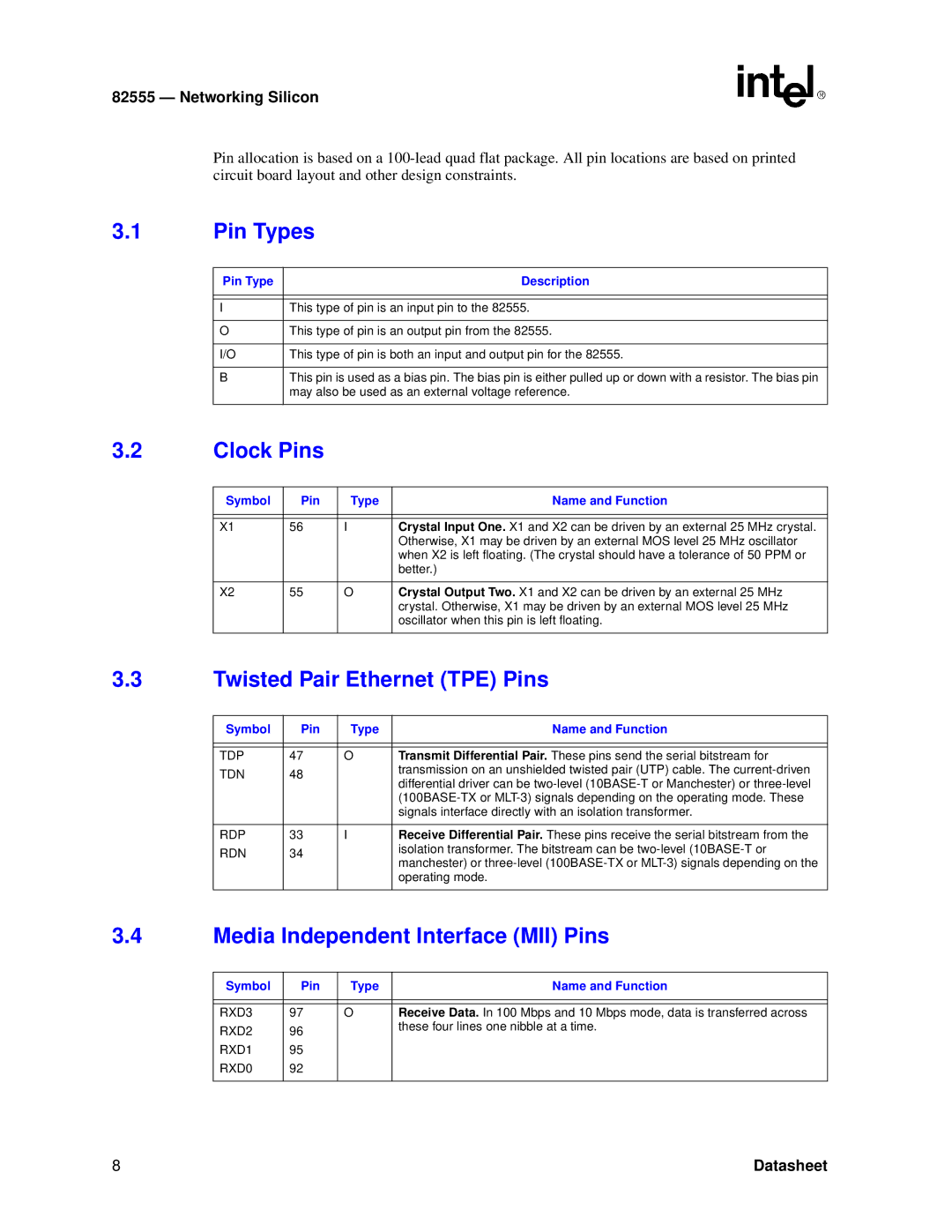
Pin allocation is based on a
3.1Pin Types
Pin Type | Description |
|
|
|
|
I | This type of pin is an input pin to the 82555. |
|
|
O | This type of pin is an output pin from the 82555. |
|
|
I/O | This type of pin is both an input and output pin for the 82555. |
BThis pin is used as a bias pin. The bias pin is either pulled up or down with a resistor. The bias pin may also be used as an external voltage reference.
3.2Clock Pins
Symbol | Pin | Type | Name and Function |
|
|
|
|
|
|
|
|
X1 | 56 | I | Crystal Input One. X1 and X2 can be driven by an external 25 MHz crystal. |
|
|
| Otherwise, X1 may be driven by an external MOS level 25 MHz oscillator |
|
|
| when X2 is left floating. (The crystal should have a tolerance of 50 PPM or |
|
|
| better.) |
|
|
|
|
X2 | 55 | O | Crystal Output Two. X1 and X2 can be driven by an external 25 MHz |
|
|
| crystal. Otherwise, X1 may be driven by an external MOS level 25 MHz |
|
|
| oscillator when this pin is left floating. |
|
|
|
|
3.3Twisted Pair Ethernet (TPE) Pins
Symbol | Pin | Type | Name and Function |
|
|
|
|
|
|
|
|
TDP | 47 | O | Transmit Differential Pair. These pins send the serial bitstream for |
TDN | 48 |
| transmission on an unshielded twisted pair (UTP) cable. The |
| differential driver can be | ||
|
|
| |
|
|
| |
|
|
| signals interface directly with an isolation transformer. |
|
|
|
|
RDP | 33 | I | Receive Differential Pair. These pins receive the serial bitstream from the |
RDN | 34 |
| isolation transformer. The bitstream can be |
| manchester) or | ||
|
|
| |
|
|
| operating mode. |
|
|
|
|
3.4Media Independent Interface (MII) Pins
Symbol | Pin | Type | Name and Function |
|
|
|
|
|
|
|
|
RXD3 | 97 | O | Receive Data. In 100 Mbps and 10 Mbps mode, data is transferred across |
RXD2 | 96 |
| these four lines one nibble at a time. |
|
| ||
RXD1 | 95 |
|
|
RXD0 | 92 |
|
|
|
|
|
|
8 | Datasheet |
