82555 — Networking Silicon
Symbol | Pin | Type | Name and Function |
|
|
|
|
|
|
|
|
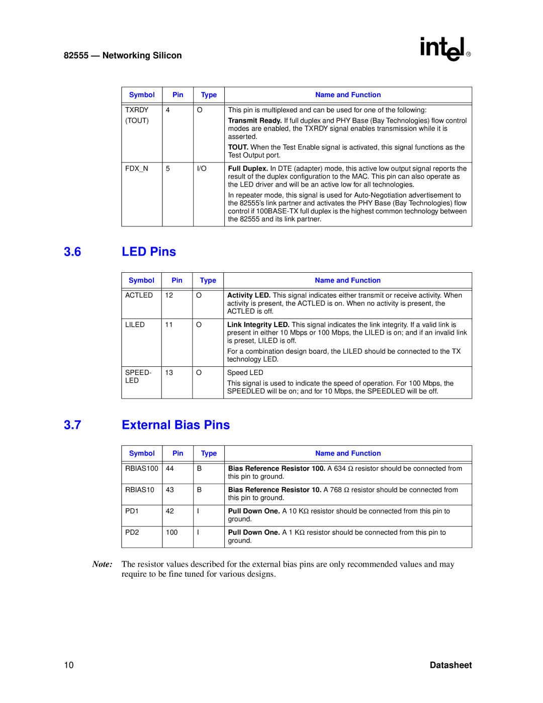
TXRDY | 4 | O | This pin is multiplexed and can be used for one of the following: |
(TOUT) |
|
| Transmit Ready. If full duplex and PHY Base (Bay Technologies) flow control |
|
|
| modes are enabled, the TXRDY signal enables transmission while it is |
|
|
| asserted. |
|
|
| TOUT. When the Test Enable signal is activated, this signal functions as the |
|
|
| Test Output port. |
|
|
|
|
FDX_N | 5 | I/O | Full Duplex. In DTE (adapter) mode, this active low output signal reports the |
|
|
| result of the duplex configuration to the MAC. This pin can also operate as |
|
|
| the LED driver and will be an active low for all technologies. |
|
|
| In repeater mode, this signal is used for |
|
|
| the 82555’s link partner and activates the PHY Base (Bay Technologies) flow |
|
|
| control if |
|
|
| the 82555 and its link partner. |
|
|
|
|
3.6LED Pins
Symbol | Pin | Type | Name and Function |
|
|
|
|
|
|
|
|
ACTLED | 12 | O | Activity LED. This signal indicates either transmit or receive activity. When |
|
|
| activity is present, the ACTLED is on. When no activity is present, the |
|
|
| ACTLED is off. |
|
|
|
|
LILED | 11 | O | Link Integrity LED. This signal indicates the link integrity. If a valid link is |
|
|
| present in either 10 Mbps or 100 Mbps, the LILED is on; and if an invalid link |
|
|
| is preset, LILED is off. |
|
|
| For a combination design board, the LILED should be connected to the TX |
|
|
| technology LED. |
|
|
|
|
SPEED- | 13 | O | Speed LED |
LED |
|
| This signal is used to indicate the speed of operation. For 100 Mbps, the |
|
|
| |
|
|
| SPEEDLED will be on; and for 10 Mbps, the SPEEDLED will be off. |
|
|
|
|
3.7External Bias Pins
Symbol | Pin | Type | Name and Function |
|
|
|
|
|
|
|
|
RBIAS100 | 44 | B | Bias Reference Resistor 100. A 634 Ω resistor should be connected from |
|
|
| this pin to ground. |
|
|
|
|
RBIAS10 | 43 | B | Bias Reference Resistor 10. A 768 Ω resistor should be connected from |
|
|
| this pin to ground. |
|
|
|
|
PD1 | 42 | I | Pull Down One. A 10 KΩ resistor should be connected from this pin to |
|
|
| ground. |
|
|
|
|
PD2 | 100 | I | Pull Down One. A 1 KΩ resistor should be connected from this pin to |
|
|
| ground. |
|
|
|
|
Note: The resistor values described for the external bias pins are only recommended values and may require to be fine tuned for various designs.
10 | Datasheet |