Raptor AT – Installation Guide
I/O Map
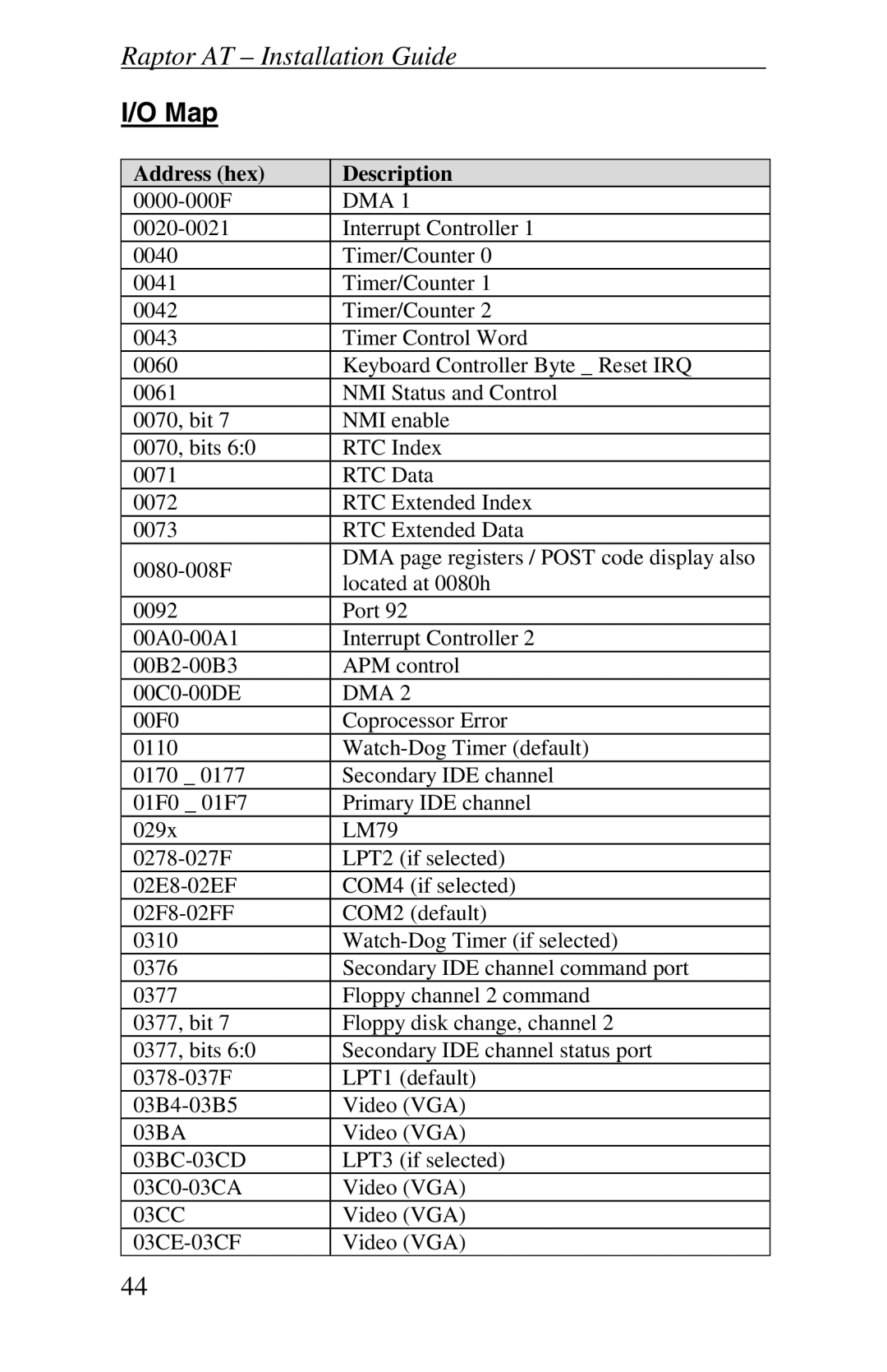
Address (hex) | Description | |
DMA 1 | ||
Interrupt Controller 1 | ||
0040 | Timer/Counter 0 | |
0041 | Timer/Counter 1 | |
0042 | Timer/Counter 2 | |
0043 | Timer Control Word | |
0060 | Keyboard Controller Byte _ Reset IRQ | |
0061 | NMI Status and Control | |
0070, bit 7 | NMI enable | |
0070, bits 6:0 | RTC Index | |
0071 | RTC Data | |
0072 | RTC Extended Index | |
0073 | RTC Extended Data | |
DMA page registers / POST code display also | ||
located at 0080h | ||
| ||
0092 | Port 92 | |
Interrupt Controller 2 | ||
APM control | ||
DMA 2 | ||
00F0 | Coprocessor Error | |
0110 | ||
0170 _ 0177 | Secondary IDE channel | |
01F0 _ 01F7 | Primary IDE channel | |
029x | LM79 | |
LPT2 (if selected) | ||
COM4 (if selected) | ||
COM2 (default) | ||
0310 | ||
0376 | Secondary IDE channel command port | |
0377 | Floppy channel 2 command | |
0377, bit 7 | Floppy disk change, channel 2 | |
0377, bits 6:0 | Secondary IDE channel status port | |
LPT1 (default) | ||
Video (VGA) | ||
03BA | Video (VGA) | |
LPT3 (if selected) | ||
Video (VGA) | ||
03CC | Video (VGA) | |
Video (VGA) |
44