Hardware Guide
M5 and M10 Internet Routers
M5 and M10 Internet Routers Hardware Guide
Table of Contents
Junos Internet Software Overview
Initial Installation
Connect the Router and Perform Initial Configuration
Replace Hardware Components Tools and Parts Required
Vii
Appendixes
Appendix B
Index
M5 and M10 Internet Routers Hardware Guide
List of Figures
List of Figures
FEB Serial Number ID Label
List of Figures
Xiii
List of Tables
List of Tables
Audience
About This Manual
Objectives
Documentation Conventions
Document Organization
Documentation Conventions
General Conventions
Juniper Networks Technical Documentation
List of Technical Publications
Xvii
List of Technical Publications
Xviii M5 and M10 Internet Routers Hardware Guide
Xix
How to Request Support
How to Request Support
Documentation Feedback
Xx M5 and M10 Internet Routers Hardware Guide
Part
M5 and M10 Internet Routers Hardware Guide
Field-Replaceable Units FRUs
System Overview
System Description
Field-Replaceable Units
Safety Requirements, Warnings, and Guidelines
Safety Requirements, Warnings, and Guidelines
Chassis
Hardware Component Overview
Front of M5 Chassis
Chassis
Rear of Chassis
Chassis Physical Specifications
Packet Forwarding Engine
Packet Forwarding Engine
Midplane
Midplane
Physical Interface Cards PICs
PIC Components
Flexible PIC Concentrators FPCs
Forwarding Engine Board FEB
FEB Components
Routing Engine
Routing Engine
Routing Engine Components
Craft Interface
Craft Interface
Alarm LEDs and Lamp Test Button
Alarm LEDs and Lamp Test Button
Routing Engine Interface Ports and Status Indicators
PIC Offline Buttons
Power Supplies
Power Supplies
AC Power Supply
AC Power Supply
Electrical Specifications for DC Power Supply
DC Power Supply
Electrical Specifications for AC Power Supply
Fan Tray
Power Supply LEDs and Self-test Button
States for Power Supply LED
Fan Tray
Cable Management System
Cable Management System
Routing Engine Software Components
Junos Internet Software Overview
IPv4 Routing Protocols
Routing Protocol Process
Routing Engine Software Components
Routing Engine Software Components
Routing and Forwarding Tables
IPv6 Routing Protocols
Routing Policy
Snmp and MIB II Processes
VPNs
Interface Process
Chassis Process
Tools for Monitoring the Software
Tools for Accessing and Configuring the Software
Management Process
Routing Engine Kernel
Software Upgrades
Software Upgrades
Packet Forwarding Engine Architecture
System Architecture Overview
Packet Forwarding Engine Architecture
Data Flow through the Packet Forwarding Engine
Routing Engine Architecture
Routing Engine Architecture
Routing Engine Architecture
Routing Engine Functions
Packets Out
34 M5 and M10 Internet Routers Hardware Guide
Part
36 M5 and M10 Internet Routers Hardware Guide
Rack Size and Strength
Prepare for Router Installation
Rack Requirements
Rack Requirements
Connection to Building Structure
Spacing of Mounting Holes
Router Environmental Tolerances
Clearance Requirements for Airflow and Hardware Maintenance
Router Environmental Tolerances
Router Environmental Tolerances
Fire Suppression Equipment
Fire Safety Requirements
Fire Safety Requirements
Fire Suppression
Power Guidelines, Requirements, and Specifications
Power Guidelines, Requirements, and Specifications
Radio Frequency Interference
Site Electrical Wiring Guidelines
Router Power Requirements
Distance Limitations for Signaling
FEB
Component Power Requirements
AC Power Cord Specifications
AC Grounding and Power Cord Specifications
DC Power and Grounding Cable Specifications
DC Grounding, Connection, and Cable Specifications
DC Power and Grounding Cable Connections
Network Cable Specifications and Guidelines
Network Cable Specifications and Guidelines
Fiber Optic and Network Cable Specifications
Signal Loss in Multimode and Single-Mode Fiber-Optic Cable
Attenuation and Dispersion in Fiber-Optic Cable
Calculating Power Budget for Fiber-Optic Cable
Estimated Values for Factors Causing Link Loss
Calculating Power Margin for Fiber-Optic Cable
Attenuate to Prevent Saturation at SONET/SDH PICs
Site Preparation Checklist
Site Preparation Checklist
Site Preparation Checklist
Site Preparation Checklist
54 M5 and M10 Internet Routers Hardware Guide
Unpack the Router
Unpack the Router
Tools Required
Generic Inventory of Router Components
Unpack the Router
Choose Front or Center Mounting
Choose Front or Center Mounting
58 M5 and M10 Internet Routers Hardware Guide
Tools and Parts Required
Install the Router
Install the Chassis into the Rack
Install the Chassis into the Rack
Connect the Router to Management Devices
Connect the Router and Perform Initial Configuration
Connect the Router to Management Devices
Connect to a Network for Out-of-Band Management
Connect PIC Cables
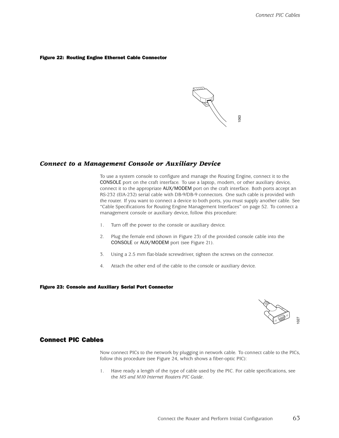
Connect to a Management Console or Auxiliary Device
Connect PIC Cables
Connect PIC Cables
Provide Power to the Router
Provide Power to the Router
Connect Power to an AC-Powered Router
Connect Power to a DC-Powered Router
Connect DC Power and Grounding Cables
Power On the Router
Provide Power to the Router
Configure the Junos Internet Software
Configure the Junos Internet Software
Configure the IP address of a DNS server
Commit the configuration to activate it on the router
72 M5 and M10 Internet Routers Hardware Guide
Part
74 M5 and M10 Internet Routers Hardware Guide
Maintain the Fan Tray
Routine Maintenance Procedures
Maintain Hardware Components
Maintain Packet Forwarding Engine Components
Maintain Packet Forwarding Engine Components
Maintain the FEB
Maintain PICs and PIC Cables
User@host show chassis fpc pic-status
Maintain the Power Supplies
Maintain the Power Supplies
Maintain the Routing Engine
Maintain the Routing Engine
80 M5 and M10 Internet Routers Hardware Guide
Tools and Parts Required
Replace Hardware Components
Replace the Fan Tray
Replace the Fan Tray
Remove the Fan Tray
Remove the Fan Tray
Install the Fan Tray
Replace Packet Forwarding Engine Components
Replace Packet Forwarding Engine Components
Replace the FEB
Remove the FEB
Remove the FEB
Install the FEB
Remove a PIC
Replace a PIC
Replace Packet Forwarding Engine Components
Remove a PIC
Install a PIC
Replace Packet Forwarding Engine Components
Replace Packet Forwarding Engine Components
Remove a PIC Cable
Replace PIC Cables
Install a PIC Cable
Replace Packet Forwarding Engine Components
Remove an SFP
Replace an SFP
Install an SFP
Replace Packet Forwarding Engine Components
Replace Power System Components
Replace Power System Components
Replace an AC Power Supply
Remove an AC Power Supply
Install an AC Power Supply
Remove an AC Power Supply
101
Disconnect and Connect AC Power
Connect AC Power to the Router
Disconnect AC Power from the Router
103
Replace an AC Power Cord
Remove a DC Power Supply
Replace a DC Power Supply
105
Install a DC Power Supply
Remove a DC Power Supply
107
Install a DC Power Supply
Disconnect and Connect DC Power
109
Disconnect DC Power from the Router
Connect DC Power to the Router
111
Replace Routing Engine Components
Replace Routing Engine Components
Remove and Insert the PC Card
Remove the PC Card
113
Insert the PC Card
Remove the PC Card
Remove the Routing Engine
Replace the Routing Engine
115
Remove the Routing Engine
Install the Routing Engine
117
Replace the Management Ethernet Cable
Replace Connectors to Routing Engine Interface Ports
Replace the Console or Auxiliary Cable
119
Serial Port Connector
121
Overview of Troubleshooting Resources
Command-Line Interface
Troubleshoot Hardware Components
LEDs on the Craft Interface
Hardware and Interface Alarm Messages
Overview of Troubleshooting Resources
LEDs
123
Chassis Alarm Messages
SONET/SDH Interface Alarm Messages
Troubleshoot Packet Forwarding Engine Components
Juniper Networks Technical Assistance Center
Troubleshoot the Fan Tray
Troubleshoot Packet Forwarding Engine Components
Troubleshoot PICs
Troubleshoot the Power System
Troubleshoot the Power System
Troubleshoot the FEB
LED on One Supply Is Off
LED on Both Supplies Is Off
127
128 M5 and M10 Internet Routers Hardware Guide
129
Safety and Regulatory Compliance Information
Definition of Safety Warning Levels
Definition of Safety Warning Levels
131
Safety Guidelines and Warnings
General Safety Guidelines and Warnings
Safety Guidelines and Warnings
Qualified Personnel Warning
133
Restricted Access Area Warning
Prevent Electrostatic Discharge Damage
135
Electrical Safety Guidelines and Warnings
AC Power Electrical Safety Guidelines
General Electrical Safety Guidelines
137
DC Power Electrical Safety Guidelines
Copper Conductors Warning
DC Power Disconnection Warning
139
DC Power Grounding Requirements and Warning
DC Power Wiring Sequence Warning
141
DC Power Wiring Terminations Warning
Grounded Equipment Warning
Midplane Energy Hazard Warning
143
Case of Electrical Accident
Power Disconnection Warning
Multiple Power Supplies Disconnection Warning
145
TN and IT Power Warning
Chassis Lifting Guidelines
Installation Safety Guidelines and Warnings
Rack-Mounting Requirements and Warnings
Installation Instructions Warning
147
Safety Guidelines and Warnings
149
Safety Guidelines and Warnings
Ramp Warning
151
General Laser Safety Guidelines
Laser and LED Safety Guidelines and Warnings
Class 1 LED Product Warning
153
Class 1 Laser Product Warning
Radiation From Open Port Apertures Warning
Laser Beam Warning
155
Maintenance and Operational Safety Guidelines and Warnings
Battery Handling Warning
Jewelry Removal Warning
Lightning Activity Warning
157
Operating Temperature Warning
Product Disposal Warning
159
Agency Approvals
Agency Approvals
Japan
Compliance Statements for EMC Requirements
Canada
European Community
United States
163
Return Procedure
Return the Router or Its Components
Locate Component Serial Numbers
Locate Component Serial Numbers
165
FEB Serial Number ID Label
PIC Serial Number ID Label
PIC Serial Number ID Label
Power Supply Serial Number ID Label
167
Routing Engine Serial Number ID Label
Pack the Router for Shipment
Pack the Router for Shipment
Pack Components for Shipment
Pack Components for Shipment
169
170 M5 and M10 Internet Routers Hardware Guide
171
Cable Connector Pinouts
RJ-45 Connector Pinouts for the Routing Engine Mgmt Port
RJ-45 Connector Pinout
RJ-48 Cable Pinouts for E1 and T1 PICs
DB-9 Connector Pinout
RJ-48 Connector to RJ-48 Connector Straight Pinout
RJ-48 Cable Pinouts for E1 and T1 PICs
173
RJ-48 Connector to RJ-48 Connector Crossover Pinout
RJ-48 Connector to DB-15 Connector Crossover Pinout
RJ-48 Connector to DB-15 Connector Straight Pinout
RJ-21 Cable Pinouts for Fast Ethernet 12-Port PIC
RJ-21 Cable Pinouts for Fast Ethernet 12-Port PIC
175
RJ-21 Pin Assignments
177
Index
178 M5 and M10 Internet Routers Hardware Guide
Index
Index
CLI
Index
EMC EMI
Packing
SONET/SDH
SFP
Wwarnings