EN37
EN37
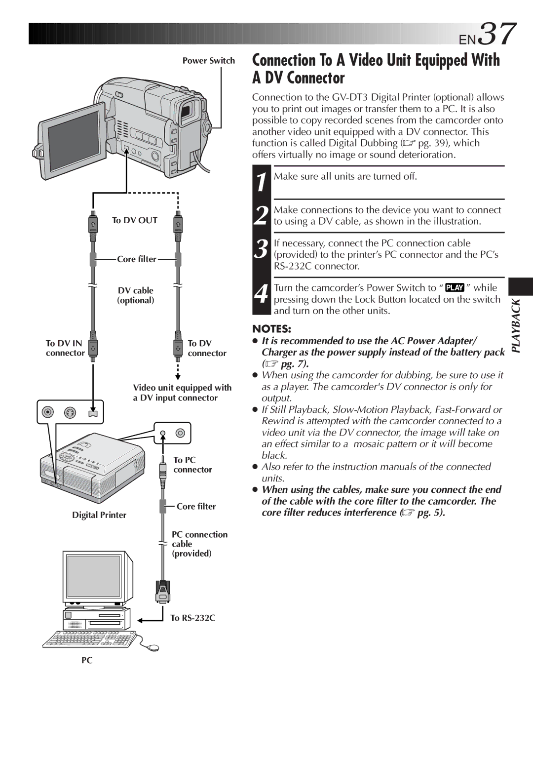
Power Switch
To DV OUT
Core filter
DV cable (optional)
To DV IN | To DV |
connector | connector |
Video unit equipped with a DV input connector
To PC connector
![]() Core filter
Core filter
Digital Printer
PC connection ![]() cable
cable
(provided)
To
Connection To A Video Unit Equipped With A DV Connector
Connection to the
1 Make sure all units are turned off.
2 Make connections to the device you want to connect to using a DV cable, as shown in the illustration.
3 If necessary, connect the PC connection cable (provided) to the printer’s PC connector and the PC’s
4 Turn the camcorder’s Power Switch to “ ![]() ” while pressing down the Lock Button located on the switch and turn on the other units.
” while pressing down the Lock Button located on the switch and turn on the other units.
NOTES:
●It is recommended to use the AC Power Adapter/
Charger as the power supply instead of the battery pack (☞ pg. 7).
●When using the camcorder for dubbing, be sure to use it as a player. The camcorder's DV connector is only for output.
●If Still Playback,
●Also refer to the instruction manuals of the connected units.
●When using the cables, make sure you connect the end
of the cable with the core filter to the camcorder. The core filter reduces interference (☞ pg. 5).
PLAYBACK
PC