2. CONTROLS, INDICATORS AND CONNECTORS
2. CONTROLS, INDICATORS AND CONNECTORS
| |||
No. | Item |
| Contents |
5 | Time/Date indication | Recorded data are displayed during playback, fast forward, and rewind. | |
|
| During recording, the data from the DV connector is displayed. | |
|
| In the stop mode, the current data is displayed. | |
|
| Whether or not the date and time should be displayed and the display style | |
|
| are set on the TIME/DATE menu screen. | |
|
| When the date and time have not been set, the following indication appears. | |
|
| – | – |
6 | Audio sampling frequency indication | The audio sampling frequency used for the recording is displayed during | |
|
| playback. |
|
|
| (32 K, 48 K, 44.1 K) | |
7 | Audio level meter indication | Displays the audio level meters during playback. | |
|
| Whether or not to display this item is set with the AUDIO item on the LCD/ | |
|
| VF (2/2) menu screen. | |
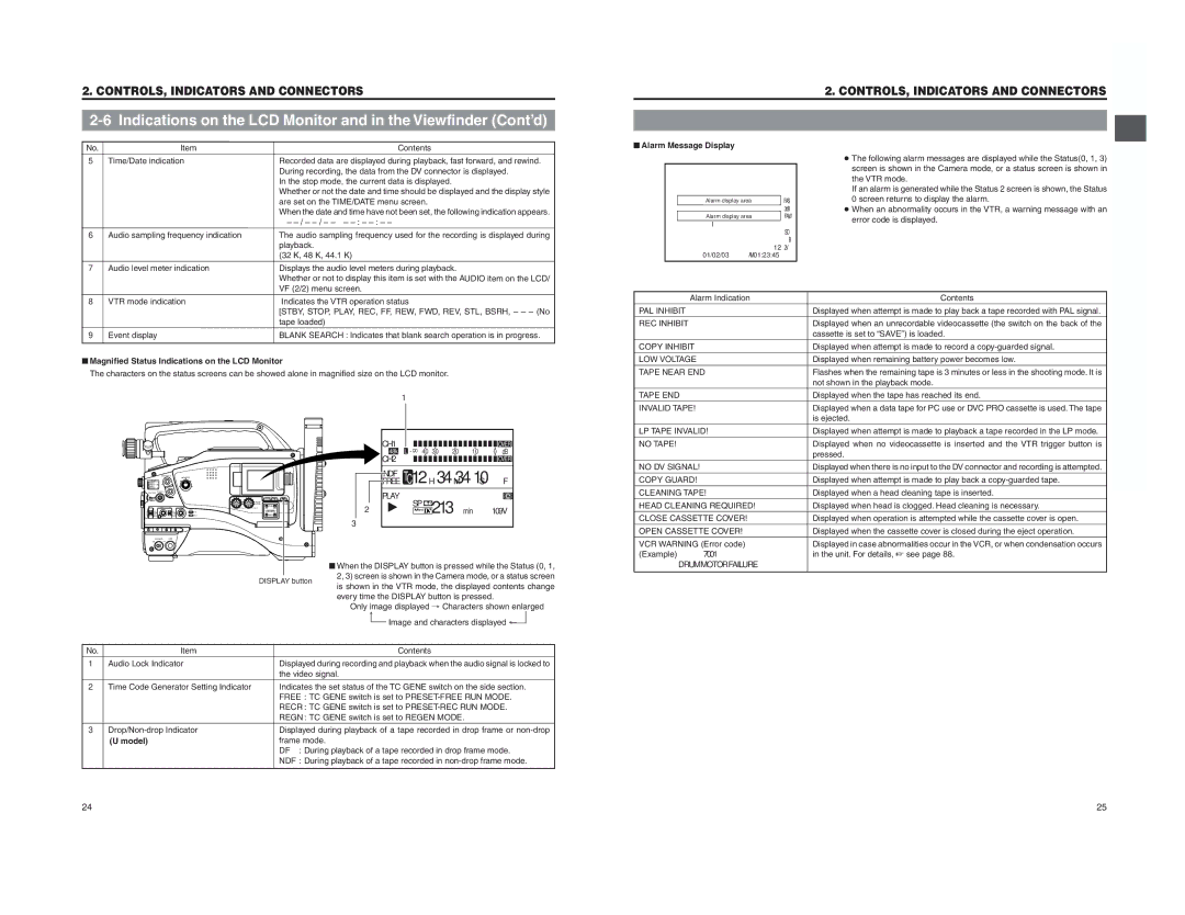
■ Alarm Message Display |
|
|
Alarm display area | FAS | |
|
| |
Alarm display area | FAW | |
| ||
|
| I |
|
| SD |
|
| B |
|
| 12.2V |
01/02/03 | AM01:23:45 | |
●The following alarm messages are displayed while the Status(0, 1, 3) screen is shown in the Camera mode, or a status screen is shown in the VTR mode.
If an alarm is generated while the Status 2 screen is shown, the Status 0 screen returns to display the alarm.
●When an abnormality occurs in the VTR, a warning message with an error code is displayed.
8 | VTR mode indication | Indicates the VTR operation status |
|
| [STBY, STOP, PLAY, REC, FF, REW, FWD, REV, STL, BSRH, – – – (No |
|
| tape loaded) |
9 | Event display | BLANK SEARCH : Indicates that blank search operation is in progress. |
■Magnified Status Indications on the LCD Monitor
The characters on the status screens can be showed alone in magnified size on the LCD monitor.
1
Alarm Indication | Contents |
PAL INHIBIT | Displayed when attempt is made to play back a tape recorded with PAL signal. |
REC INHIBIT | Displayed when an unrecordable videocassette (the switch on the back of the |
| cassette is set to “SAVE”) is loaded. |
COPY INHIBIT | Displayed when attempt is made to record a |
LOW VOLTAGE | Displayed when remaining battery power becomes low. |
TAPE NEAR END | Flashes when the remaining tape is 3 minutes or less in the shooting mode. It is |
| not shown in the playback mode. |
TAPE END | Displayed when the tape has reached its end. |
INVALID TAPE! | Displayed when a data tape for PC use or DVC PRO cassette is used. The tape |
| is ejected. |
LP TAPE INVALID! | Displayed when attempt is made to playback a tape recorded in the LP mode. |
EDITSEARCH
MONITOR
FILTER 3200K 5600K / 5600K 5600K /
SHUTTER STATUS ![]()
MENU
AUDIO
LEVEL
![]() CH-1
CH-1![]() CH-2
CH-2
POWER VTR
ONOFF
DISPLAY button
CH1 |
|
|
|
|
|
|
|
|
|
|
|
|
|
|
|
| OVER | |
48k | L - ∞ 40 30 20 10 | 0 | dB | |||||||||||||||
CH2 |
|
|
|
|
|
|
|
|
|
|
|
|
|
|
|
| OVER | |
NDF | C12H34M3410S F | |||||||||||||||||
FREE | ||||||||||||||||||
T |
|
|
|
|
|
|
|
|
|
|
|
|
|
|
| |||
PLAY | SP |
|
|
|
|
|
|
|
|
|
|
|
|
| e |
| ||
|
|
|
|
|
|
|
|
|
|
|
|
|
| |||||
|
|
|
|
|
|
|
|
|
|
|
|
|
|
|
| |||
|
|
|
|
|
|
|
|
|
|
|
|
|
|
|
| |||
2 |
| 213min |
|
| 109V. | |||||||||||||
|
|
|
|
|
| |||||||||||||
|
|
|
|
|
|
| ||||||||||||
3
■When the DISPLAY button is pressed while the Status (0, 1, 2, 3) screen is shown in the Camera mode, or a status screen is shown in the VTR mode, the displayed contents change every time the DISPLAY button is pressed.
Only image displayed → Characters shown enlarged
↑
Image and characters displayed ←
NO TAPE! |
| Displayed when no videocassette is inserted and the VTR trigger button is |
|
| pressed. |
NO DV SIGNAL! |
| Displayed when there is no input to the DV connector and recording is attempted. |
COPY GUARD! |
| Displayed when attempt is made to play back a |
CLEANING TAPE! | Displayed when a head cleaning tape is inserted. | |
HEAD CLEANING REQUIRED! | Displayed when head is clogged. Head cleaning is necessary. | |
CLOSE CASSETTE COVER! | Displayed when operation is attempted while the cassette cover is open. | |
OPEN CASSETTE COVER! | Displayed when the cassette cover is closed during the eject operation. | |
VCR WARNING (Error code) | Displayed in case abnormalities occur in the VCR, or when condensation occurs | |
(Example) | 7001 | in the unit. For details, ☞ see page 88. |
DRUMMOTORFAILURE |
| |
No. | Item |
| Contents |
1 | Audio Lock Indicator | Displayed during recording and playback when the audio signal is locked to | |
|
| the video signal. | |
2 | Time Code Generator Setting Indicator | Indicates the set status of the TC GENE switch on the side section. | |
|
| FREE : TC GENE switch is set to | |
|
| RECR : TC GENE switch is set to | |
|
| REGN : TC GENE switch is set to REGEN MODE. | |
3 | Displayed during playback of a tape recorded in drop frame or | ||
| (U model) | frame mode. | |
|
| DF | : During playback of a tape recorded in drop frame mode. |
|
| NDF : During playback of a tape recorded in | |
24
25