2. CONTROLS, INDICATORS AND CONNECTORS |
|
2. CONTROLS, INDICATORS AND CONNECTORS
i | PUSH |
| |
u |
|
y |
|
|
|
|
|
PHONES | DV | REAR AUDIO IN | TALLY | q |
|
t |
|
|
| LINE OUT | |
|
|
|
| ||
| DC IN |
|
|
| Y/C OUT MONITOR OUT |
DC OUT |
|
|
|
| o |
|
|
|
|
| |
|
|
|
|
| |
r | e | w |
|
|
|
MEMO:
●The volume of the alarm sound is set with the ALARM VR LEVEL item on the OTHERS (2/2) menu screen.
●When using a stereotype jack and stereo sound should be output, the following setting should be performed.
Set the MONITOR SELECT switch to “MIX”.
Set the AUDIO MONITOR item on the AUDIO/VIDEO menu screen to STEREO.
6 | [DV] connector |
|
| Using a DV cable (optional), a digital video component with | |
| DV connector can be connected here. |
|
| This connector is used for input and output of the DV signal | |
| or to input the VTR control signal from a digital video | |
| component with DV connector. |
|
| To record the DV signal from this connector, set the unit to | |
| the VTR mode. (Press the MODE switch | ^ on page 13 |
| upward to turn on the VTR indicator.) |
|
| ● Camera mode: |
|
| The DV compressed signal (IEEE1394) of the camera | |
| image is output. |
|
| ● VTR mode: |
|
| The DV input signal from this connector can be recorded | |
| on tape. During playback, the tape playback DV | |
| compressed signal is output. | (U model) |
|
| |
Using a DV cable (optional), a digital video component with DV connector can be connected here. This connector is used for output of the DV signal or to input the VTR control signal from a digital video component with DV connector.
●Camera mode:
The DV compressed signal (IEEE1394) of the camera image is output.
●VTR mode:
During playback, the tape playback DV compressed sig-
nal is output. | (E model) |
|
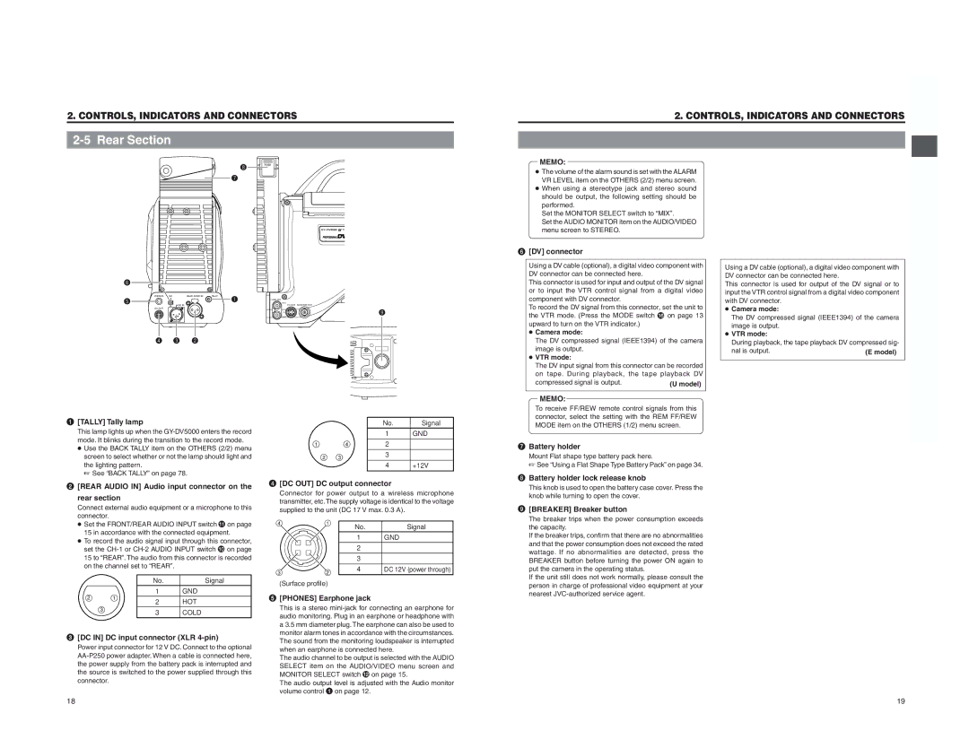
1 | [TALLY] Tally lamp |
| This lamp lights up when the |
| mode. It blinks during the transition to the record mode. |
| ● Use the BACK TALLY item on the OTHERS (2/2) menu |
| screen to select whether or not the lamp should light and |
| the lighting pattern. |
| ☞ See “BACK TALLY” on page 78. |
2 | [REAR AUDIO IN] Audio input connector on the |
| rear section |
| Connect external audio equipment or a microphone to this |
| connector. |
|
| No. | Signal |
|
| 1 | GND |
1 | 4 | 2 | — |
2 | 3 | 3 | — |
|
| ||
|
| 4 | +12V |
4 | [DC OUT] DC output connector |
| Connector for power output to a wireless microphone |
| transmitter, etc. The supply voltage is identical to the voltage |
| supplied to the unit (DC 17 V max. 0.3 A). |
MEMO: To receive FF/REW remote control signals from this connector, select the setting with the REM FF/REW MODE item on the OTHERS (1/2) menu screen.
7 Battery holder Mount Flat shape type battery pack here.
☞See “Using a Flat Shape Type Battery Pack” on page 34.
8 Battery holder lock release knob | |
| This knob is used to open the battery case cover. Press the |
| knob while turning to open the cover. |
9 | [BREAKER] Breaker button |
| The breaker trips when the power consumption exceeds |
● Set the FRONT/REAR AUDIO INPUT switch ! on page | |
15 in accordance with the connected equipment. | |
● To record the audio signal input through this connector, | |
set the | |
15 to “REAR”. The audio from this connector is recorded | |
on the channel set to “REAR”. |
|
No. | Signal |
1GND
4 | 1 |
3 | 2 |
(Surface profile) | |
No. 1 2 3 4
Signal GND — — DC 12V (power through)
the capacity. |
If the breaker trips, confirm that there are no abnormalities |
and that the power consumption does not exceed the rated |
wattage. If no abnormalities are detected, press the |
BREAKER button before turning the power ON again to |
put the camera in the operating status. |
If the unit still does not work normally, please consult the |
person in charge of professional video equipment at your |
nearest |
2 |
| 1 | 2 | HOT |
|
|
| ||
| 3 |
| 3 | COLD |
|
|
|
3 | [DC IN] DC input connector (XLR |
| Power input connector for 12 V DC. Connect to the optional |
| |
| the power supply from the battery pack is interrupted and |
| the source is switched to the power supplied through this |
| connector. |
5 | [PHONES] Earphone jack |
| This is a stereo |
| audio monitoring. Plug in an earphone or headphone with |
| a 3.5 mm diameter plug. The earphone can also be used to |
| monitor alarm tones in accordance with the circumstances. |
| The sound from the monitoring loudspeaker is interrupted |
| when an earphone is connected here. |
| The audio channel to be output is selected with the AUDIO |
| SELECT item on the AUDIO/VIDEO menu screen and |
| MONITOR SELECT switch @ on page 15. |
| The audio output level is adjusted with the Audio monitor |
| volume control 1 on page 12. |
18 | 19 |