2. CONTROLS, INDICATORS AND CONNECTORS
| ||||
● Status 1 |
|
|
| |
In addition to the information on the Status 0 screen, this screen displays the following items. |
| |||
No. | Item |
| Contents |
|
0 | Time Code (TC)/User’s Bits (UB) indication | Indicates the time code (h:m:s:frame) or user’s bits data. | ||
|
| (Example) Time code | TC 00 : 00 : 00 : 00 | |
|
|
|
| |
|
| User’s bits | UB FF EE DD 20 | Drop frame: Dot (.) |
|
|
| ||
|
| Whether or not to display this item is set with the TC/UB item on the LCD/ | ||
|
| VF (2/2) menu screen. Whether the time code or user’s bits should be shown | ||
|
| is selected with the COUNTER switch inside the side cover. | ||
A | Remaining tape indication | Remaining tape indication (displayed in | ||
|
| This indicator blinks when remaining tape time is equivalent to less than 3 | ||
|
| minutes. |
|
|
|
| Whether or not to display this item is set with the TAPE REMAIN item on | ||
|
| the LCD/VF (2/2) menu screen. |
| |
*When inserting a
*The remaining tape indication is to be regarded only as a guide.
*When the unit is used at low temperatures, it may take a while before the indication of the remaining tape time appears.
B | Audio sampling frequency indication | 32 K | : | Indicated when the AUDIO MODE item on the AUDIO/VIDEO menu | |
|
|
|
| screen is set to 32 K. (Audio is recorded with | |
|
|
|
| sampling.) | |
|
| 48 K | : | Indicated when the AUDIO MODE item on the AUDIO/VIDEO menu | |
|
|
|
| screen is set to 48 K. (Audio is recorded with | |
|
|
|
| sampling.) | |
C | Audio level meter indication | Displays the | |||
|
| Whether or not to display this item is set with the AUDIO DISPLAY item on | |||
|
| the LCD/VF (2/2) menu. | |||
D | VTR mode indication | STBY |
| : | In record standby mode |
|
| REC |
| : | During recording |
|
| ED.FWD : | Edit search in forward direction | ||
|
| ED.REV : | Edit search in reverse direction | ||
|
| PLAY |
| : | During playback |
|
| FF |
| : | During fast forward |
|
| REW |
| : | During rewind |
|
| STL |
| : | During still picture playback mode |
|
| BSRH | : | During blank search | |
|
| FWD |
| : | During playback in forward direction (FWD1: About X5 speed, |
|
| REV |
| : | FWD2: About ×9 speed, FWD3: About X20 speed) |
|
|
| During playback in reverse direction (REV1: About X5 speed, | ||
|
| STOP |
| : | REV2: About ×9 speed, REV3: About X20 speed) |
|
|
| Stop mode (Tape protect mode) | ||
|
| EJECT | : | Cassette being ejected | |
|
| – – – |
| : | No tape loaded |
E | Iris indicator display | ▲ : Iris set higher than normal | |||
■: Iris set to normal
▼: Iris set lower than normal
F | Iris | Indicates the |
|
|
|
| OPEN, F2, F2.8, F4, F5.6, F8, F11, F16, CLOSE |
| |
|
| It is not displayed when the lens is removed. For some lenses, no display | ||
|
| appears. |
|
|
|
| The indication can be switched ON/OFF with the F.NO/IRIS IND. item on | ||
|
| the LCD/VF (1/2) menu screen. |
|
|
G | Filter position indication | Indicates the current filter position |
|
|
|
| FIL1, FIL2, FIL3, FIL4 |
|
|
|
| The indication can be switched ON/OFF with the FILTER item on the LCD/ | ||
|
| VF (1/2) menu screen. |
|
|
H | Standard audio level indication | The level at which audio is recorded on the tape is indicated by “■”. | ||
|
| |||
|
| ☞ See “AUDIO REF. LEVEL” on page 72. | ❘ | ❘ |
|
|
| CH 1 ■ ■ ■ ■ ■ | |
|
|
| CH 1 ■ ■ ■ ■ ■ – – – + | |
|
|
| CH 2 ■ ■ ■ ■ ■ – – – + | |
22
| 2. CONTROLS, INDICATORS AND CONNECTORS | |||
● Status 2 |
|
|
|
|
This screen displays the camera setup statuses. |
|
|
| |
Event display is not available while this screen is displayed. |
|
|
| |
Indication | Indication Contents | |||
FULL AUTO | ON, OFF |
|
|
|
GAIN |
|
|
| |
SHUTTER | OFF, 1/7.5, 1/15, 1/30, 1/60, 1/100, 1/250. 1/500, 1/1000, 1/2000, 1/4000, 1/10000 (STEP), V.SCAN 1/60.1 to | |||
| 1/2084.6 (VARIABLE), EEI (in ALC mode) (U model) |
|
|
|
WHITE BAL | A, B, PRESET, FAW |
|
|
|
IRIS LEVEL | BACK L, NORMAL, SPOT L |
|
|
|
ZEBRA |
|
|
| |
FILTER | 3200K, 5600K+1/8ND, 5600K, 5600K+1/64ND |
|
|
|
REMAIN | Remaining tape time (min) or tape type (Example: 95 min ( | )) |
|
|
|
|
|
| |
| (when using MiniDV cassette), (when using standard cassette), | DVCAM | (when using DVCAM cassette) | |
*DVCAM indicates IC Memory compatible DVCAM cassette.
In the case of other DVCAM cassette than IC Memory compatible cassette, ![]() or
or ![]() is indicated.
is indicated.
AUDIO | Audio sampling frequency and audio level adjustment method (Example) 32K (CH1 Å CH2 ˜ ) Å (Auto) |
| ˜ (Manual) |
● Status 3 This screen only displays date and time, event display and warning indications.
*Whether or not date and time should be displayed and the display style are set on the TIME DATE MENU screen. ☞ page 43 “Displaying the Time and Date on the Screen”
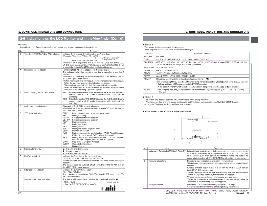
■Status Screen in VTR MODE (DV Signal Input Mode)
|
|
|
|
|
| 1 |
|
|
|
|
|
|
|
|
|
|
|
|
| ||
|
|
| 00:00:00:00 |
|
| |||||
|
|
|
|
|
|
| 20min | 3 | ||
| 9 |
| Event display area |
|
|
|
| |||
|
|
|
|
|
|
|
|
| 6 | |
|
|
|
|
|
| 48k | 12.2V |
|
| 4 |
| 8 | PLAY | 01/02/03 | AM01:23:45 |
|
| ||||
|
|
| 7 |
|
| 5 |
|
|
|
|
No. | Item |
|
|
|
|
|
|
| Contents | |
1 | Indication of Time Code (TC)/User’s Bits (UB) | In the playback mode, the recorded time code (hour, minute, second, frame) | ||||||||
|
|
| is displayed. Whether or not to display this item is set with the TC/UB item | |||||||
|
|
| on the LCD/VF (2/2) menu screen. Whether to show the time code or the | |||||||
|
|
| user’s bits is selected with the COUNTER switch inside the side cover. | |||||||
2 | Remaining tape time |
| Remaining tape indication (displayed in | |||||||
|
|
| This indicator blinks when remaining tape time is equivalent to less than 3 | |||||||
|
|
| minutes. |
|
|
|
|
| ||
|
|
| Whether or not to display this item is set with the TAPE REMAIN item on | |||||||
|
|
| the LCD/VF (2/2) menu screen. |
|
| |||||
|
|
| * When inserting a | |||||||
|
|
| When the tape has been run, the indication will appear. | |||||||
|
|
| * The remaining tape indication is to be used only as a guide. | |||||||
|
|
| * When the unit is used at low temperatures, it may take a while before the | |||||||
|
|
| indication of the remaining tape time appears. | |||||||
3 | Voltage indication | (Example) 12.2 V : Indicates battery voltage in 0.1 V steps. |
| |
|
| * This indicator blinks when the remaining battery power is low. |
| |
|
| OFF, 1/6.25, 1/12.5, 1/25, 1/50, 1/120, 1/250, 1/500, 1/1000, 1/2000, 1/4000, 1/10000 (STEP), ← | ||
|
| V.SCAN 1/50.1 to 1/2067.8 (VARIABLE), EEI (in ALC mode) | (E model) | 23 |