9. USING EXTERNAL COMPONENTS
Connecting the
9. USING EXTERNAL COMPONENTS
When Using the
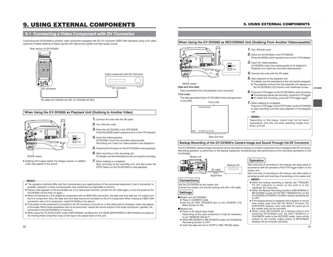
Rear section of
MODE
VTR
CAM
1. 2.
3.
Turn ON both units.
Place the
Insert the videocassettes.
| Video component with DV Connector |
PHONES DVREAR AUDIO IN TALLY |
|
DC IN |
|
DC OUT |
|
DV connector | DV connector |
| |
DV cable |
|
When Using the
POWER VTR
MODE switch |
|
|
Date and time data: |
|
|
Data transmitted from the playback unit is recorded. | ||
Time code: |
|
|
The data generated by the | ||
is recorded. | Time code | |
| ||
|
|
|
| TC00:00:00:00 | |
4. Connect the units with the DV cable.
5. Start playback on the playback unit. For details, see the instructions to the unit used for playback.
●The playback picture from the playback unit appears on the
6. Press the VTR trigger on the
■To temporarily pause the recording, press the VTR trigger.
■To restart the recording, press the VTR trigger again.
7. When dubbing is completed. Press the VTR trigger or the STOP button on the
(U model)
MODE
1. 2. 3.
4.
Connect the units with the DV cable.
Turn ON both units.
Place the
Insert the videocassettes.
REC | 01/02/03 01:23:45 | |||
|
|
|
|
|
|
|
|
| |
|
| Date and time | ||
MEMO: Depending on the player, sound may not be heard momentarily from this unit when switching modes from STILL to PLAY.
VTR
CAM
POWER VTR
MODE switch
5. 6.
Press the PLAY button on the
Start recording on the recording unit. For details, see the instructions to the unit used for recording.
Backup Recording of the
The
●Dubbing still images makes the images coarser. In addition, noise may appear in the sound.
7.
When dubbing is completed. Stop recording on the recording unit, and then press the STOP button on the
Backup unit DV cable
Signal flow
Operation
Start and stop of recording on the backup unit takes place in accordance with the operation of the VTR trigger button on the master unit. Start and stop of recording on the backup unit takes place in accordance with start and stop of recording on the master unit. MEMO:
MEMO:
●The operation methods differ with the characteristics and specifications of the connected equipment. Even if connection is possible, operation or data communication may sometimes be impossible to perform.
●If block noise appears or the sound falls out, try to disconnect and then connect the DV cable again, or turn the power to the
●When connecting to a
●If the power to the component connected to the DV connector is turned on, or the video input is changed, noise may appear in the audio. When these operations have to be performed, reduce the sound volume of the audio component, speaker, etc., connected to the
●When using the TC DUPLICATE mode of
60
Connections
Use the
Settings
■Master unit
●Place in CAMERA mode.
●Set the DV REC TRIGGER item on the OTHERS (1/2) Menu Screen to ON.
■Backup unit
●Place in DV signal input mode.
* | Depending on the used component, it may be necessary |
| to set “REMOTE SELECT”. |
●When
●Insert the tape and set to STOP or REC PAUSE status.
●When the backup recording is started, the “TRIGGER TO DV” indication is shown on the LCD or in the viewfinder for 3 seconds.
●When the Backup Recording function of
●If the backup device is equipped with a feature to record time codes input from the DV IN/OUT terminal (TC DUPLICATE feature), time code data the same as on the master side can be recorded.
●When using
(backup will be correctly recorded).
61