11. MENU SCREENS |
|
| ||
|
|
| ||
Item |
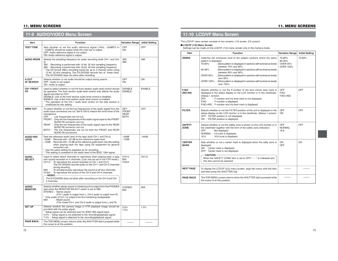
| Function | Variation Range | Initial Setting |
TEST TONE | Sets whether or not the audio reference signal (1kHz, | OFF | OFF | |
| ON |
| ||
| OFF: Audio reference signal is not output. |
|
| |
| ON: Audio reference signal is output. |
|
| |
AUDIO MODE | Selects the sampling frequency for audio recording (both | 32K | 48K | |
| 2) |
| 48K |
|
| 32K | : Recording is performed with |
|
|
| 48K | : Recording is performed with |
|
|
*The DV format offers recording tracks for up to 4 channel when using
A.OUT | Selects whether or not audio should be output during search. | OFF | ON |
AT SEARCH | OFF : Audio is not output | ON |
|
| ON : Audio is output |
|
|
11. MENU SCREENS
11-10 LCD/VF Menu Screen
The LCD/VF menu screen consists of two screens. (1/2 screen, 2/2 screen)
■LCD/VF (1/2) Menu Screen
Settings can be made on the LCD/VF (1/2) menu screen only in the Camera mode.
Item |
| Function | Variation Range | Initial Setting |
ZEBRA | Switches the luminance level of the subject sections where the zebra | |||
| pattern is displayed. |
| ||
| : Zebra pattern is displayed in sections with luminance levels | OVER 95% |
| |
|
| between 70% and 80%. | OVER 100% |
|
| : Zebra pattern is displayed in sections with luminance levels |
|
| |
|
| between 85% and 90%. |
|
|
| OVER 95% | : Zebra pattern is displayed in sections with luminance levels |
|
|
|
| over 95%. |
|
|
| OVER 100% | : Zebra pattern is displayed in sections with luminance levels |
|
|
|
| over 100%. |
|
|
CH1 FRONT VR
WIND CUT
AUDIO REF. LEVEL
Used to select whether or not the front section audio level control should | DISABLE | ENABLE | ||
be operative. The front section audio level control only affects the audio | ENABLE |
| ||
signal recorded on CH1. |
|
| ||
DISABLE: Use of the front section audio level control is disabled. |
|
| ||
ENABLE: Use of the front section audio level control is enabled. |
|
| ||
* The operation of the |
|
| ||
unaffected by this setting. |
|
| ||
To select whether or not the low frequencies of the audio signal from the | OFF | OFF | ||
audio input connectors are cut. Set to ON to reduce the wind noise of the | FRONT |
| ||
microphone. | REAR |
| ||
OFF | : | Low frequencies are not cut. | BOTH |
|
FRONT : | Only the low frequencies of the audio signal input to the FRONT |
|
| |
REAR | : | AUDIO IN connector are cut. |
|
|
Only the low frequencies of the audio signal input to the REAR |
|
| ||
BOTH | : | AUDIO IN connector are cut. |
|
|
The low frequencies are cut for both the FRONT and REAR |
|
| ||
|
| AUDIO IN connectors. |
|
|
Sets the reference audio level of the tape (both | ||||
: | Records with |
| ||
F.NO/ | Selects whether or not the | OFF | OFF | ||
IRIS IND. | displayed in the status display on the LCD monitor or in the viewfinder. | F.NO |
| ||
| (Status 1 screen) | F.NO+IND. |
| ||
| OFF | : |
|
| |
| F.NO | : |
|
| |
| F.NO+IND. : |
|
| ||
FILTER | Selects whether or not the FILTER position of the unit is displayed in the | OFF | OFF | ||
| status display on the LCD monitor or in the viewfinder. (Status 1 screen) | ON |
| ||
| OFF : | FILTER position is not displayed. |
|
| |
| ON : | FILTER position is displayed. |
|
| |
SAFETY | Selects whether or not the safety zone is shown on the LCD monitor or in | OFF | OFF | ||
ZONE | the viewfinder together with the form of the safety zone indication. | NORMAL |
| ||
| OFF | : | Not displayed | 16:9 |
|
| NORMAL : | 4:3 zone is displayed. |
|
| |
| 16:9 | : | 16:9 zone is displayed. |
|
|
AUDIO SELECT
: | Records with | |
|
| when playing back the tape using DV equipment for general |
|
| consumer use. |
*Use the same setting for playback as for recording.
*This setting is unrelated to the audio level of the IEEE 1394 signal.
Used to select which channels to reproduce when playing back a tape | CH1/2 | CH1/2 | ||
with sound recorded on 4 channels. (Can only be set in the VTR mode.) | MIX |
| ||
CH1/2 | : | To reproduce the sound recorded on | CH3/4 |
|
|
| The |
|
|
MIX | : | during shooting. |
|
|
To simultaneously reproduce the sound of all four channels. |
|
| ||
CH3/4 | : | To reproduce the sound of the |
|
|
CENTER
MARK
NEXT PAGE
Sets whether or not a center mark is displayed when the safty zone is displayed. ON : Center mark is displayed. OFF : Center mark is not displayed.
CAUTION: When the SAFETY ZONE item is set to OFF, “- -
To display the LCD/VF (2/2) menu screen, align the cursor with this item and then press the SHUTTER dial.
ON | ON |
OFF |
|
AUDIO MONITOR
SET UP
PAGE BACK
MEMO: | |
The | |
4 channels. | |
Selects whether stereo sound or mixed sound is output from the PHONES | |
jack when the MONITOR SELECT switch is set to MIX. | |
STEREO | : Stereo sound |
| |
* Only audio of | |
MIX | : Mixed sound |
| (The mixed |
Selects whether the camera image or VTR playback image should be | |
provided with the setup signal. | |
*Setup signal can be selected even for IEEE1394 signal input. 0.0% : Setup signal is not attached to the recording/playback signal. 7.5% : Setup signal is attached to the recording/playback signal.
The TOP MENU screen returns when the SHUTTER dial is pressed while the cursor is at this position.
STEREO | MIX |
MIX |
|
0.0% | 7.5% |
7.5% |
|
PAGE BACK
The TOP MENU screen returns when the SHUTTER dial is pressed while the cursor is at this position.
72
73