5. PREPARATIONS
5-5 Charging the Built-in Battery
6. SETTING AND ADJUSTMENTS BEFORE SHOOTING
6-1 Camera Settings
The
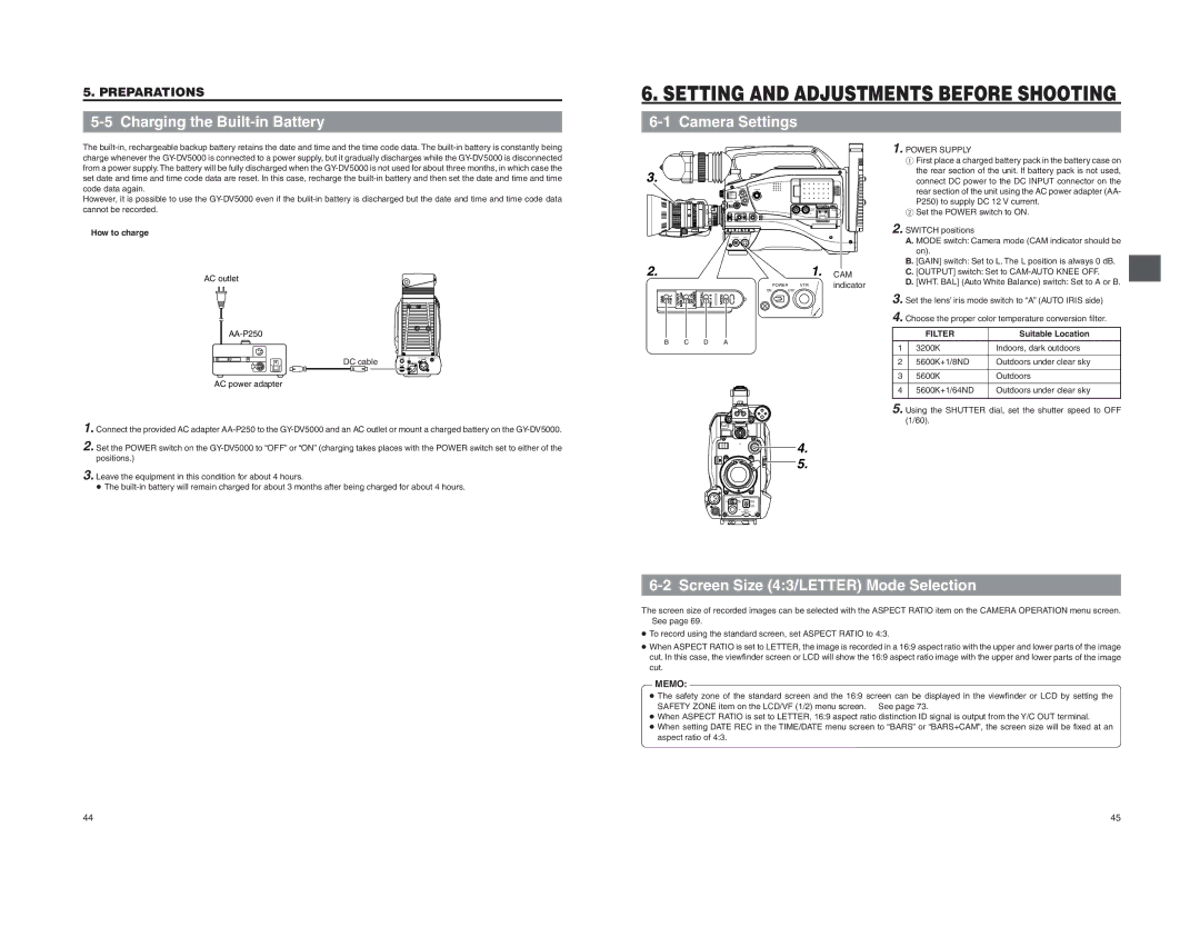
■How to charge
AC outlet
DC cable
AC power adapter
1. Connect the provided AC adapter
2. Set the POWER switch on the
3. Leave the equipment in this condition for about 4 hours. ● The
3. |
POWER VTR
2. |
|
|
|
|
|
|
| 1. | CAM |
|
|
|
|
|
|
|
|
| |
|
|
|
|
|
| POWER | VTR |
| indicator |
|
| OUTPUT BARS CAM | OFF ON AUTOKNEE | WHT.BAL |
| ON | OFF |
|
|
GAIN | H M L | PRST A B | MODE |
|
|
| |||
| B |
| C |
| D | A |
|
|
|
VF | 4. |
| 5. |
1. POWER SUPPLY
1First place a charged battery pack in the battery case on the rear section of the unit. If battery pack is not used,
connect DC power to the DC INPUT connector on the rear section of the unit using the AC power adapter (AA- P250) to supply DC 12 V current.
2Set the POWER switch to ON.
2. SWITCH positions |
| |
| A. MODE switch: Camera mode (CAM indicator should be | |
| on). |
|
| B. [GAIN] switch: Set to L. The L position is always 0 dB. | |
| C. [OUTPUT] switch: Set to | |
| D. [WHT. BAL] (Auto White Balance) switch: Set to A or B. | |
3. Set the lens’ iris mode switch to “A” (AUTO IRIS side) | ||
4. Choose the proper color temperature conversion filter. | ||
| FILTER | Suitable Location |
1 | 3200K | Indoors, dark outdoors |
2 | 5600K+1/8ND | Outdoors under clear sky |
3 | 5600K | Outdoors |
4 | 5600K+1/64ND | Outdoors under clear sky |
5. Using the SHUTTER dial, set the shutter speed to OFF | ||
| (1/60). |
|
ZEBRA
AUDIO
LEVELE
6-2 Screen Size (4:3/LETTER) Mode Selection
The screen size of recorded images can be selected with the ASPECT RATIO item on the CAMERA OPERATION menu screen.
☞See page 69.
● To record using the standard screen, set ASPECT RATIO to 4:3.
● When ASPECT RATIO is set to LETTER, the image is recorded in a 16:9 aspect ratio with the upper and lower parts of the image cut. In this case, the viewfinder screen or LCD will show the 16:9 aspect ratio image with the upper and lower parts of the image cut.
MEMO: ● The safety zone of the standard screen and the 16:9 screen can be displayed in the viewfinder or LCD by setting the SAFETY ZONE item on the LCD/VF (1/2) menu screen. ☞ See page 73. ● When ASPECT RATIO is set to LETTER, 16:9 aspect ratio distinction ID signal is output from the Y/C OUT terminal. ● When setting DATE REC in the TIME/DATE menu screen to “BARS” or “BARS+CAM”, the screen size will be fixed at an aspect ratio of 4:3.
44
45