4. POWER SUPPLY
5. PREPARATIONS
5-1 Turning the Power ON
MENU
AUDIO
LEVEL
![]() CH-1
CH-1![]() CH-2
CH-2
LCD monitor
LOW VOLTAGE
10.5V
TALLY lamp
To display the remaining battery power accurately, set the BATTERY TYPE item on the OTHERS (2/2) menu screen in accordance with the type of the battery pack in use.
☞See “BATTERY TYPE” on page 78.
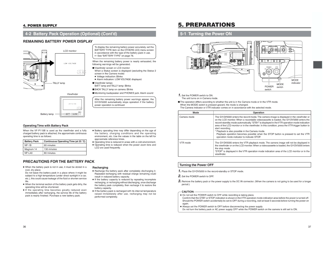
When the remaining battery power is nearly exhausted, the following warnings will be generated.
■ Viewfinder screen or LCD monitor |
When a Status screen is displayed (excluding the Status 2 |
screen in the Camera mode) |
● Voltage indication: Blinks |
● Alarm indication: LOW VOLTAGE displayed. |
■ Viewfinder lamps |
BATT lamp and TALLY lamp: Blinks |
■ BACK TALLY lamp on camera: Blinks |
■ Monitoring loudspeaker and PHONES jack: Alarm sound |
AUTO IRIS | FULL AUTO | BLACK |
| LOLUX |
| BACK L |
| STRETCH | MODE |
|
| VTR | ||
| NORMAL |
| NORMAL | |
| SPOT L |
|
| CAM |
|
|
|
|
POWER VTR
POWER VTR | ON | OFF |
|
|
| MODE |
|
| MODE | indicator |
POWER |
| ||
switch |
| ||
switch |
| ||
|
| ||
Battery lamp
Viewfinder
LOW VOLTAGE
10.5V
REC BATT ALARM
After the remaining battery power warnings appear, the |
power operation is continued. |
1. Set the POWER switch to ON. The unit turns on in Camera mode.
■The operation differs according to whether the unit is in the Camera mode or in the VTR mode. When the MODE switch is pressed upward, the mode is changed.
The Camera indicator or VTR indicator comes on in accordance with the selected mode.
Mode | Operation |
Camera mode | The |
| on the LCD monitor. When a recordable videocassette is loaded, the |
|
Operating Time with Battery Pack | |
When the | |
charged battery pack is attached, the approximate continuous | |
operating time is as follows: | |
Battery Pack | Continuous Operating Time (at 25 ˚C) |
| 60 minutes |
Magnum 14 | 130 minutes |
80 minutes | |
●Battery operating time may differ depending on the age of the battery, charging conditions and the operating environment, etc. Use the values in the table on the left for approximate reference times.
●Operating time is reduced in areas with a cold environment.
●Operating time is reduced when the power zoom lens and LCD are used frequently.
| area of the LCD monitor or in the viewfinder. In this condition, press the VTR trigger button to |
| start recording. |
| * Playback is also possible in the Camera mode. |
| Playback operation becomes possible when the STOP button is pressed to set the VTR |
| operation mode indicator to indicate STOP. |
VTR mode | The |
| the viewfinder or on the LCD monitor. When a videocassette is loaded, the |
| the stop mode. |
| “STOP” is displayed in the VTR operation mode indication area of the LCD monitor or in the |
| viewfinder. |
PRECAUTIONS FOR THE BATTERY PACK
Turning the Power OFF
●When the battery pack is not in use, it must be stored in a cool, dry place.
Do not leave the battery pack in a place where it might be subject to a high temperature (under direct sunlight in a car, etc.), this could cause leakage of the fluid or shorten service life.
●When the terminal section of the battery pack gets dirty, the operating time will be shortened.
●If the operating time becomes greatly reduced even immediately after recharging, the service life of the battery pack is nearly finished. Purchase a new battery pack.
Recharging
●Recharge the battery pack after completely discharging it. Repeated recharging with residual charge remaining could result in reduced battery capacity.
●If the battery capacity is reduced by repeating incomplete recharging, or recharging without discharging, once discharge the battery pack completely, then recharge it to restore the battery capacity.
●If the battery pack is recharged with its internal temperature raised immediately after use, recharging may not be performed completely.
1. Place the
2. Set the POWER switch to OFF.
3. Remove the battery pack or the power supply to the DC IN connector. (When the camera is not going to be used for a longer period.)
CAUTION:
●Do not set the POWER switch to OFF while recording is taking place.
Confirm that the STBY or STOP indication is shown in the VTR operation mode indication area before the power is turned off. Should the POWER switch accidentally be set to OFF during a recording, wait at least 5 seconds before turning the power on again.
●Always set the POWER switch to OFF before disconnecting the power supply
Do not turn the battery pack or AC power supply OFF while the POWER switch on the camera is still set to ON.
36
37