1.7 Service Views
2
1
3
8
9
10
7 |
| 4 |
| 11 |
6 | 5 |
| 12 | |
|
| 16 | ||
|
|
| 15 | |
|
| 14 |
| |
|
|
|
| |
| 13 |
|
|
|
21 | 17 |
kps_002.eps
| 20 | 18 | |
|
| 19 |
|
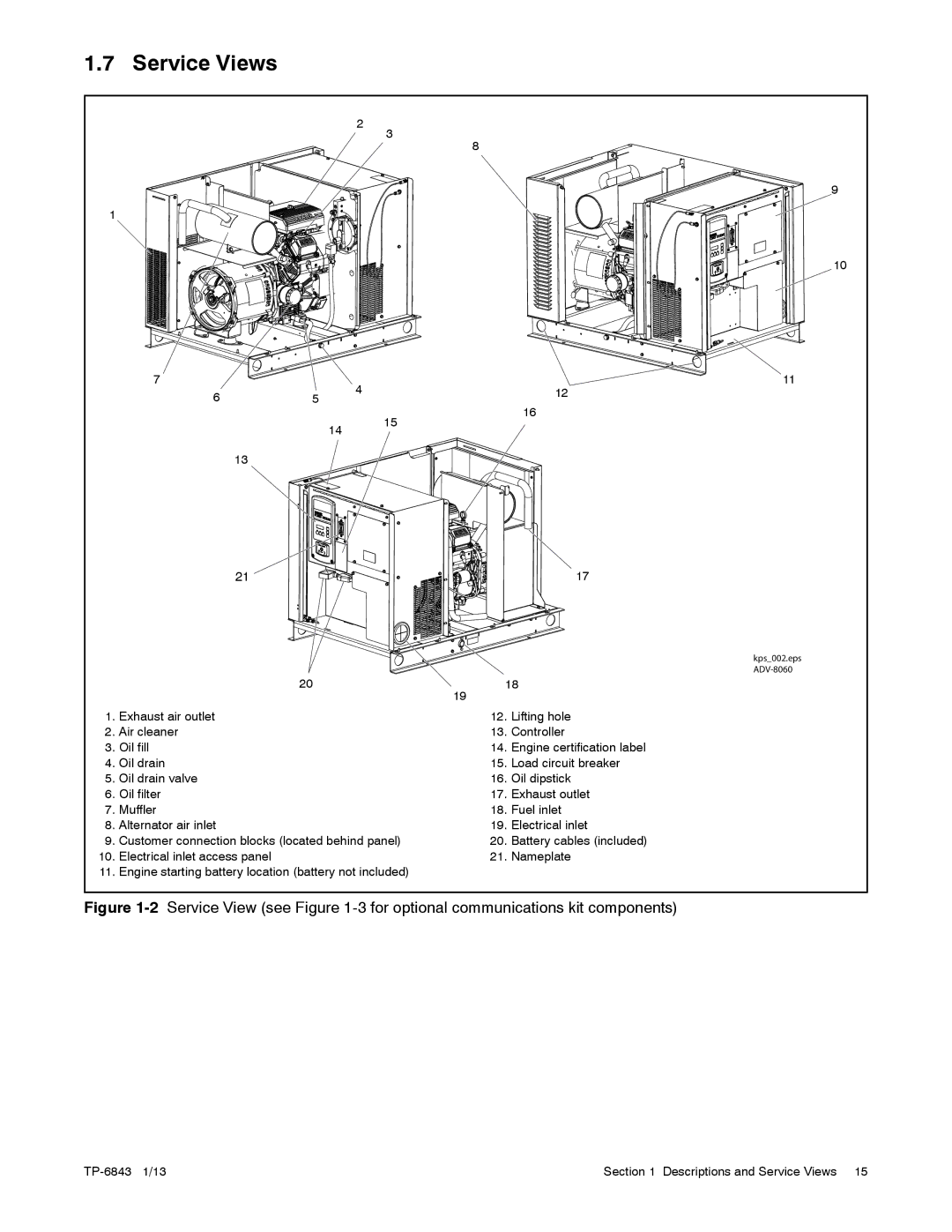
1. | Exhaust air outlet | 12. | Lifting hole |
2. | Air cleaner | 13. | Controller |
3. | Oil fill | 14. | Engine certification label |
4. | Oil drain | 15. | Load circuit breaker |
5. | Oil drain valve | 16. | Oil dipstick |
6. | Oil filter | 17. | Exhaust outlet |
7. | Muffler | 18. | Fuel inlet |
8. | Alternator air inlet | 19. | Electrical inlet |
9. | Customer connection blocks (located behind panel) | 20. | Battery cables (included) |
10. | Electrical inlet access panel | 21. | Nameplate |
11. | Engine starting battery location (battery not included) |
|
|
Figure 1-2 Service View (see Figure 1-3 for optional communications kit components)
Section 1 Descriptions and Service Views 15 |
