3.2.3LCD Display
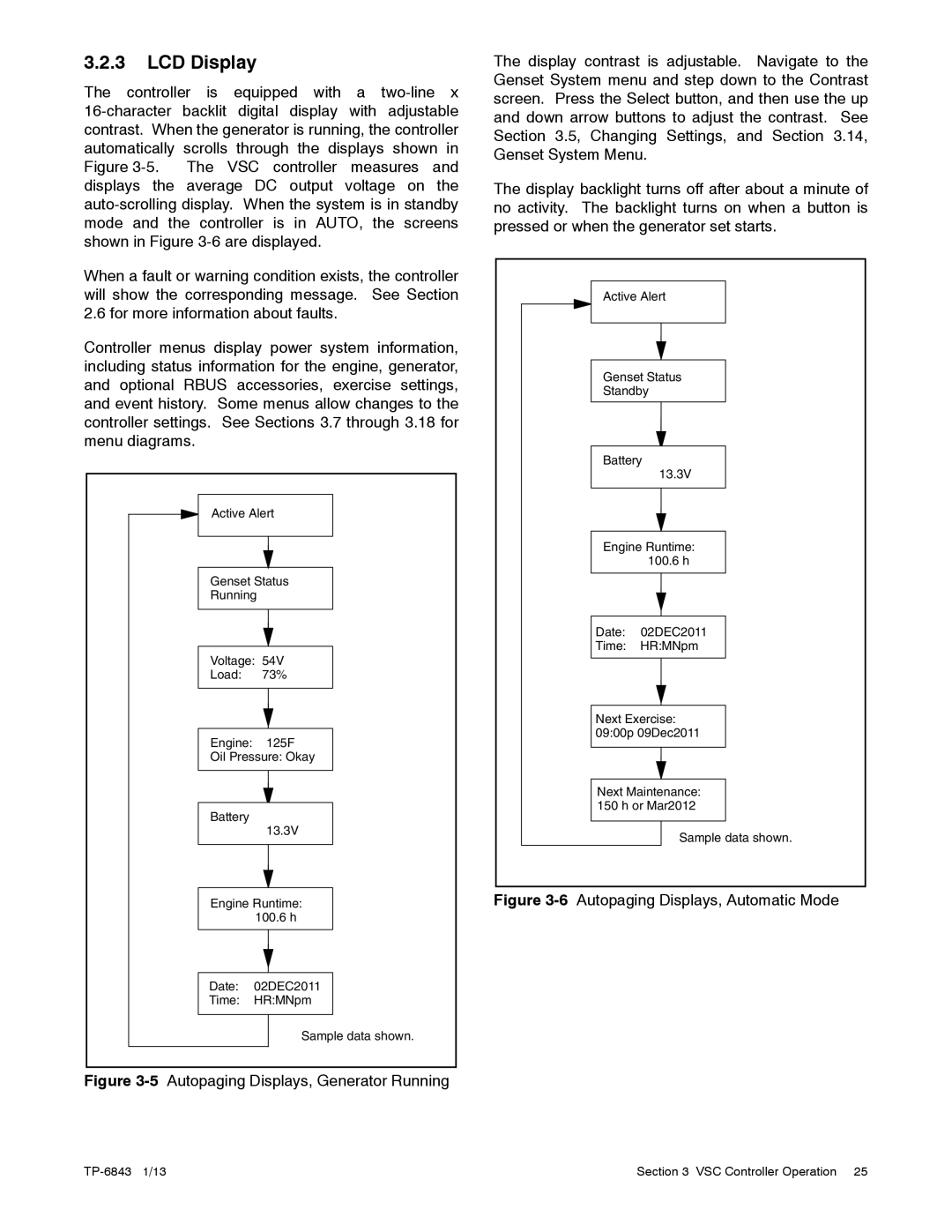
The controller is equipped with a
When a fault or warning condition exists, the controller will show the corresponding message. See Section 2.6 for more information about faults.
Controller menus display power system information, including status information for the engine, generator, and optional RBUS accessories, exercise settings, and event history. Some menus allow changes to the controller settings. See Sections 3.7 through 3.18 for menu diagrams.
Active Alert
Genset Status
Running
Voltage: 54V
Load: 73%
Engine: 125F
Oil Pressure: Okay
Battery
13.3V
Engine Runtime: 100.6 h
Date: 02DEC2011
Time: HR:MNpm
Sample data shown.
Figure 3-5 Autopaging Displays, Generator Running
The display contrast is adjustable. Navigate to the Genset System menu and step down to the Contrast screen. Press the Select button, and then use the up and down arrow buttons to adjust the contrast. See Section 3.5, Changing Settings, and Section 3.14, Genset System Menu.
The display backlight turns off after about a minute of no activity. The backlight turns on when a button is pressed or when the generator set starts.
Active Alert
Genset Status
Standby
Battery
13.3V
Engine Runtime: 100.6 h
Date: 02DEC2011
Time: HR:MNpm
Next Exercise: 09:00p 09Dec2011
Next Maintenance: 150 h or Mar2012
Sample data shown.
tp6804
Figure 3-6 Autopaging Displays, Automatic Mode
Section 3 VSC Controller Operation 25 |
