2.Controls and connectors
A. Top panel
1 | 2 | 3 | 4 5 |
6
7
8
9
10 |
11 |
12 |
13 |
14 |
15 |
16
17
2220 21 1918
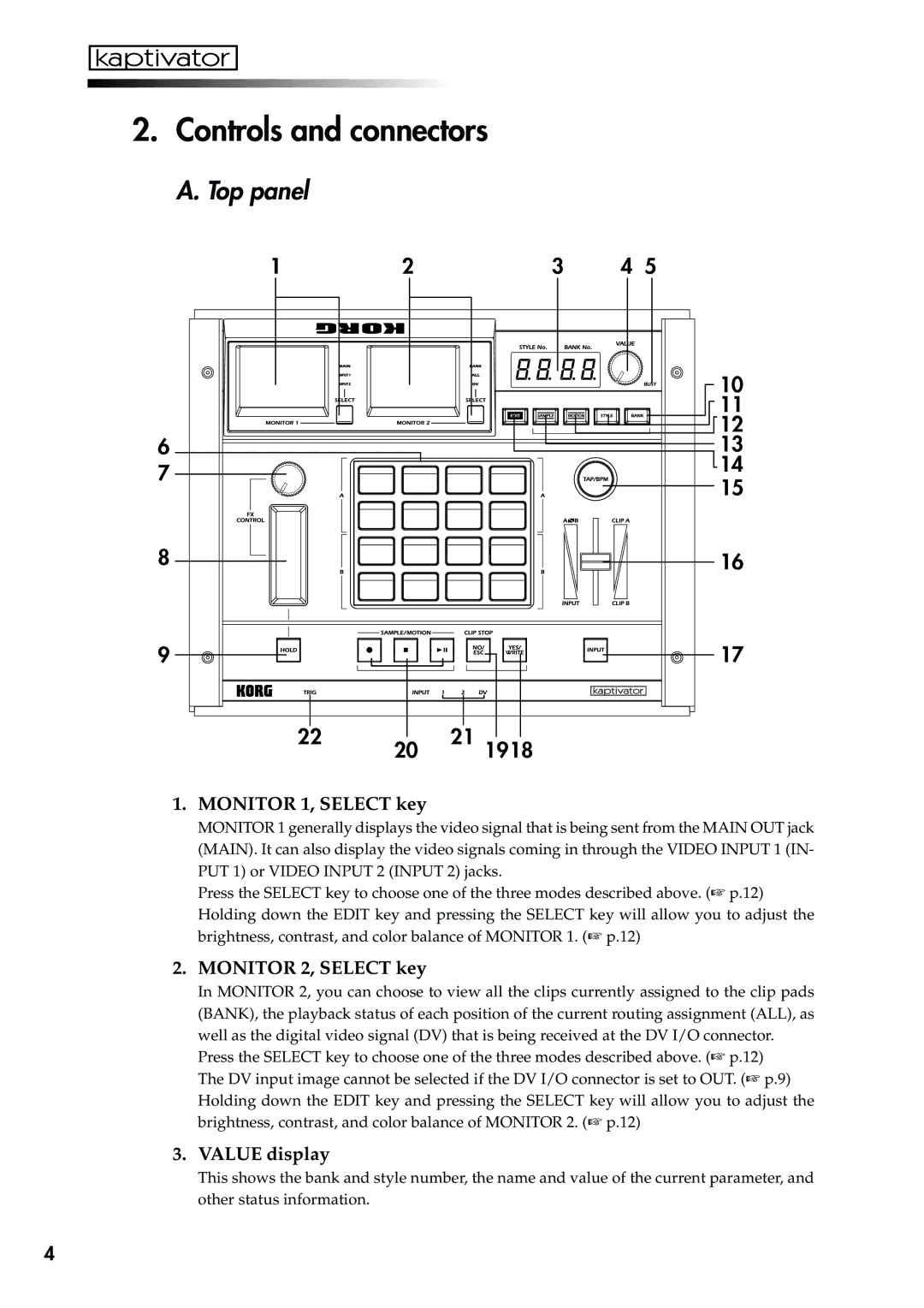
1.MONITOR 1, SELECT key
MONITOR 1 generally displays the video signal that is being sent from the MAIN OUT jack (MAIN). It can also display the video signals coming in through the VIDEO INPUT 1 (IN- PUT 1) or VIDEO INPUT 2 (INPUT 2) jacks.
Press the SELECT key to choose one of the three modes described above. (☞ p.12) Holding down the EDIT key and pressing the SELECT key will allow you to adjust the brightness, contrast, and color balance of MONITOR 1. (☞ p.12)
2. MONITOR 2, SELECT key
In MONITOR 2, you can choose to view all the clips currently assigned to the clip pads (BANK), the playback status of each position of the current routing assignment (ALL), as well as the digital video signal (DV) that is being received at the DV I/O connector.
Press the SELECT key to choose one of the three modes described above. (☞ p.12) The DV input image cannot be selected if the DV I/O connector is set to OUT. (☞ p.9) Holding down the EDIT key and pressing the SELECT key will allow you to adjust the brightness, contrast, and color balance of MONITOR 2. (☞ p.12)
3. VALUE display
This shows the bank and style number, the name and value of the current parameter, and other status information.
4
