3-4 Administration Guide
Identify the Connectors and Attach the Cables
Identify the connectors on the back panel and attach the necessary Netopia cables.
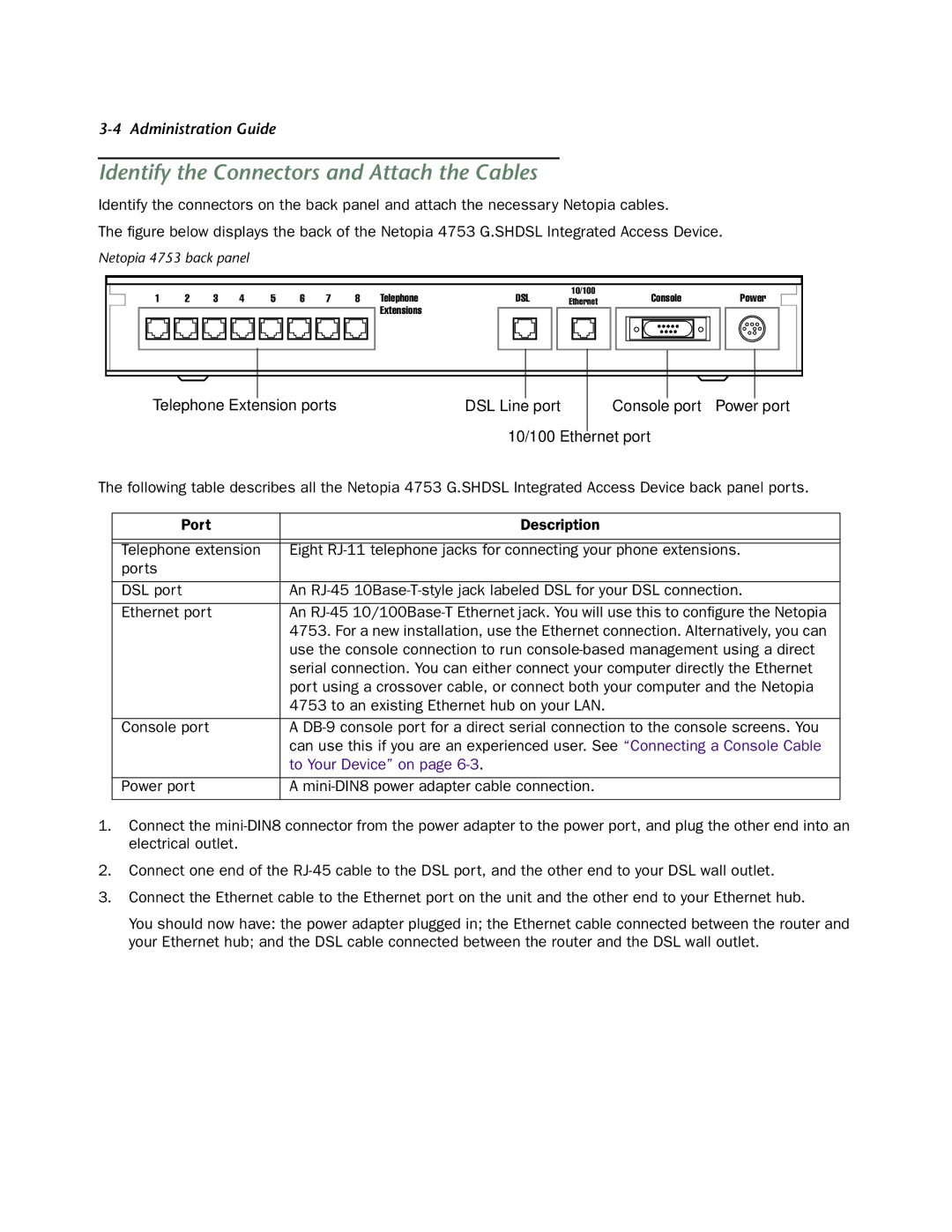
The figure below displays the back of the Netopia 4753 G.SHDSL Integrated Access Device.
Netopia 4753 back panel
1 | 2 | 3 | 4 | 5 | 6 | 7 | 8 | Telephone | DSL | 10/100 | Console | Power |
Ethernet |
Extensions
Telephone Extension ports | DSL Line port | Console port | Power port |
10/100 Ethernet port
The following table describes all the Netopia 4753 G.SHDSL Integrated Access Device back panel ports.
Port | Description |
|
|
|
|
Telephone extension | Eight |
ports |
|
|
|
DSL port | An |
|
|
Ethernet port | An |
| 4753. For a new installation, use the Ethernet connection. Alternatively, you can |
| use the console connection to run |
| serial connection. You can either connect your computer directly the Ethernet |
| port using a crossover cable, or connect both your computer and the Netopia |
| 4753 to an existing Ethernet hub on your LAN. |
|
|
Console port | A |
| can use this if you are an experienced user. See “Connecting a Console Cable |
| to Your Device” on page |
|
|
Power port | A |
|
|
1.Connect the
2.Connect one end of the
3.Connect the Ethernet cable to the Ethernet port on the unit and the other end to your Ethernet hub.
You should now have: the power adapter plugged in; the Ethernet cable connected between the router and your Ethernet hub; and the DSL cable connected between the router and the DSL wall outlet.