Making the Physical Connections
Netopia 4753 Status Lights
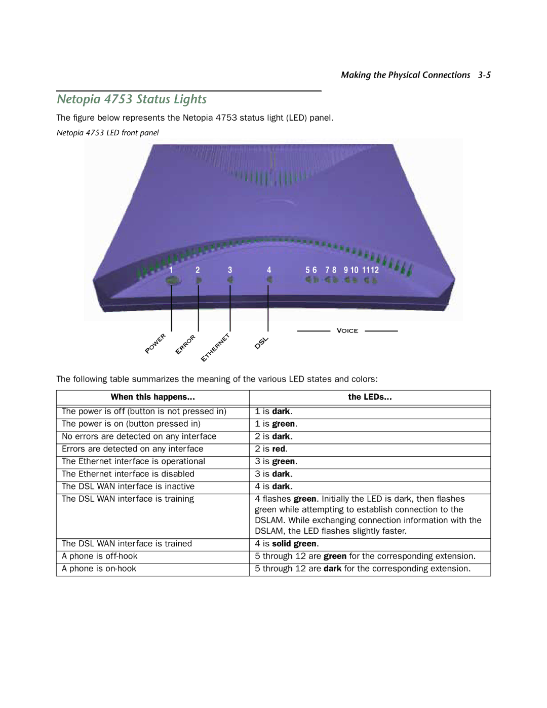
The figure below represents the Netopia 4753 status light (LED) panel.
Netopia 4753 LED front panel
1 | 2 | 3 | 4 | 5 6 | 7 8 | 9 10 1112 |
VOICE
P | OWER | E | RROR |
| THERNET | DSL |
|
| |||||
|
|
|
|
| ||
|
|
|
| E |
|
|
The following table summarizes the meaning of the various LED states and colors:
When this happens... | the LEDs... |
|
|
|
|
The power is off (button is not pressed in) | 1 is dark. |
The power is on (button pressed in) | 1 is green. |
|
|
No errors are detected on any interface | 2 is dark. |
|
|
Errors are detected on any interface | 2 is red. |
|
|
The Ethernet interface is operational | 3 is green. |
|
|
The Ethernet interface is disabled | 3 is dark. |
|
|
The DSL WAN interface is inactive | 4 is dark. |
|
|
The DSL WAN interface is training | 4 flashes green. Initially the LED is dark, then flashes |
| green while attempting to establish connection to the |
| DSLAM. While exchanging connection information with the |
| DSLAM, the LED flashes slightly faster. |
|
|
The DSL WAN interface is trained | 4 is solid green. |
|
|
A phone is | 5 through 12 are green for the corresponding extension. |
|
|
A phone is | 5 through 12 are dark for the corresponding extension. |
|
|
