EXPLATION FOR MICOM CIRCUIT
1-2. Oscillation circuit
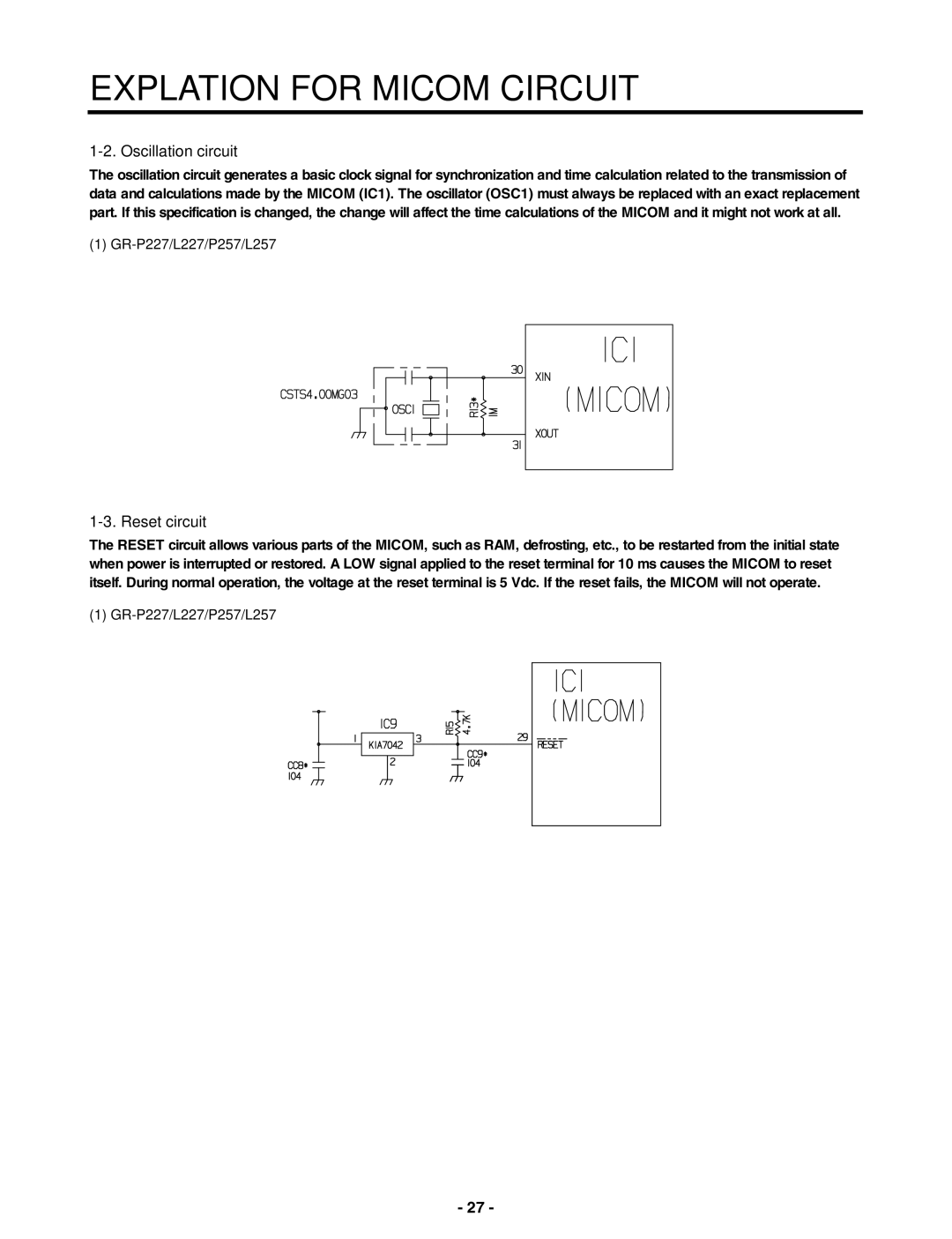
The oscillation circuit generates a basic clock signal for synchronization and time calculation related to the transmission of data and calculations made by the MICOM (IC1). The oscillator (OSC1) must always be replaced with an exact replacement part. If this specification is changed, the change will affect the time calculations of the MICOM and it might not work at all.
(1) GR-P227/L227/P257/L257
1-3. Reset circuit
The RESET circuit allows various parts of the MICOM, such as RAM, defrosting, etc., to be restarted from the initial state when power is interrupted or restored. A LOW signal applied to the reset terminal for 10 ms causes the MICOM to reset itself. During normal operation, the voltage at the reset terminal is 5 Vdc. If the reset fails, the MICOM will not operate.
(1)
- 27 -