EXPLATION FOR MICOM CIRCUIT
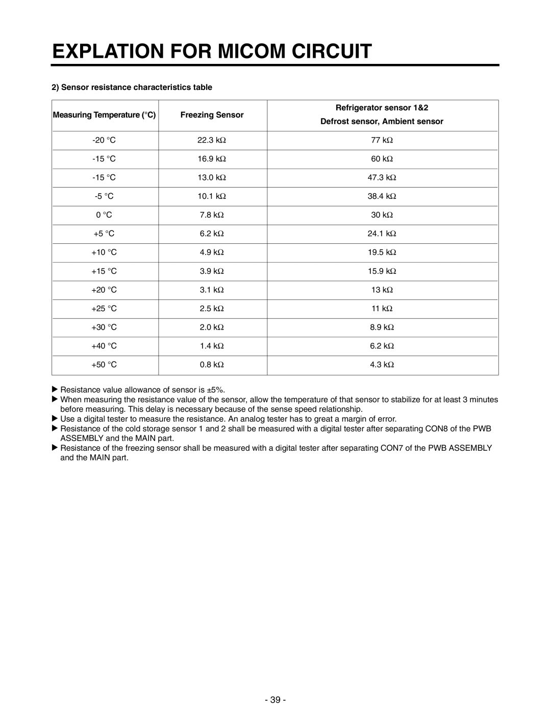
2) Sensor resistance characteristics table
Measuring Temperature (°C) | Freezing Sensor | Refrigerator sensor 1&2 | |
Defrost sensor, Ambient sensor | |||
|
| ||
|
|
| |
22.3 kΩ | 77 kΩ | ||
|
|
| |
16.9 kΩ | 60 kΩ | ||
|
|
| |
13.0 kΩ | 47.3 kΩ | ||
|
|
| |
10.1 kΩ | 38.4 kΩ | ||
|
|
| |
0 °C | 7.8 kΩ | 30 kΩ | |
|
|
| |
+5 °C | 6.2 kΩ | 24.1 kΩ | |
|
|
| |
+10 °C | 4.9 kΩ | 19.5 kΩ | |
|
|
| |
+15 °C | 3.9 kΩ | 15.9 kΩ | |
|
|
| |
+20 °C | 3.1 kΩ | 13 kΩ | |
|
|
| |
+25 °C | 2.5 kΩ | 11 kΩ | |
|
|
| |
+30 °C | 2.0 kΩ | 8.9 kΩ | |
|
|
| |
+40 °C | 1.4 kΩ | 6.2 kΩ | |
|
|
| |
+50 °C | 0.8 kΩ | 4.3 kΩ | |
|
|
|
uResistance value allowance of sensor is ±5%.
uWhen measuring the resistance value of the sensor, allow the temperature of that sensor to stabilize for at least 3 minutes before measuring. This delay is necessary because of the sense speed relationship.
uUse a digital tester to measure the resistance. An analog tester has to great a margin of error.
uResistance of the cold storage sensor 1 and 2 shall be measured with a digital tester after separating CON8 of the PWB ASSEMBLY and the MAIN part.
uResistance of the freezing sensor shall be measured with a digital tester after separating CON7 of the PWB ASSEMBLY and the MAIN part.
- 39 -
