Manuals
/
LG Electronics
/
Kitchen Appliance
/
Refrigerator
LG Electronics
GR-P257/L257 Exploded View, FREEZER DOOR PART GR-P227/L227/P257/L257, #Ev#
Models:
GR-P257/L257
GR-P227/L227
1
91
99
99
Download
99 pages
61.41 Kb
88
89
90
91
92
93
94
95
<
>
Troubleshooting
Specs
Sensor resistance characteristics table
Install
Replacement of water filter
When connecting directly to the water tap
Problems
Reset circuit
Water Valve Disassembly Method
Explain the procedure and principles of ice maker operation
Page 91
Image 91
#EV#
EXPLODED VIEW
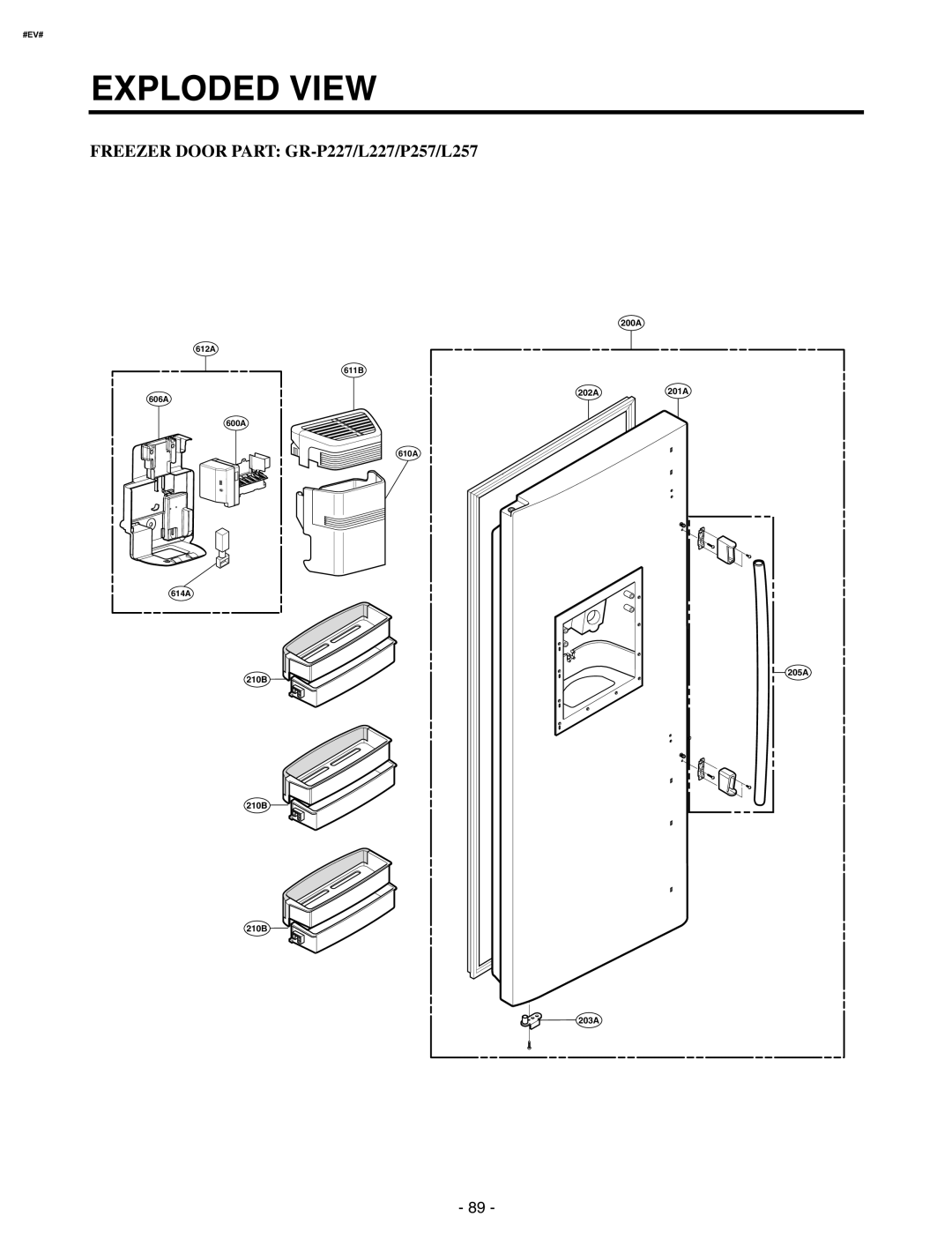
FREEZER DOOR PART:
GR-P227/L227/P257/L257
612A
611B
606A
600A
614A
210B
210B
210
B
200A
202A
201A
610A
205A
203A
- 89 -
Page 90
Page 92
Page 91
Image 91
Page 90
Page 92
Contents
MODEL GR-P227/L227 GR-P257/L257
http//eic.lgservice.com
SERVICE MANUAL
REFRIGERATOR
HOW TO INSTALL THE REFRIGERATOR
CONTENTS
WARNINGS AND PRECAUTIONS FOR SAFETY
SPECIFICATIONS
WARNINGS AND PRECAUTIONS FOR SAFETY
SPECIFICATIONS
SPECIFICATIONS
1. Ref No. GR-P227
SPECIFICATIONS
SPECIFICATIONS
2. Ref No. GR-L227
SPECIFICATIONS
SPECIFICATIONS
SPECIFICATIONS
1. Ref No. GR-P257
SPECIFICATIONS
SPECIFICATIONS
SPECIFICATIONS
2. Ref No. GR-L257
SPECIFICATIONS
SPECIFICATIONS
1. Ref No. GR-P227/GR-P257 INTERNAL FILTER
PARTS IDENTIFICATION
Freezer Refrigerator compartment compartment
Cover PWB
2. Ref No. GR-P227/GR-P257 EXTERNAL FILTER
PARTS IDENTIFICATION
Freezer Refrigerator compartment compartment
PARTS IDENTIFICATION
3. Ref No. GR-P227/GR-P257 INTERNAL FILTER
Freezer Refrigerator compartment compartment
PARTS IDENTIFICATION
4. Ref No. GR-P227/GR-P257 EXTERNAL FILTER
Freezer Refrigerator compartment compartment
2. If the height of freezer door is higher than that of
HOW TO INSTALL REFRIGERATOR
1. How to Adjust Door Height of Refrigerator
1. If the height of freezer door is lower than that of
2-1. When connecting directly to the water tap
2. How to Install Water Pipe
HOW TO INSTALL REFRIGERATOR
Before Installation
Cold Water
HOW TO INSTALL REFRIGERATOR
1. Connection of Pipe Connector A and B
Hot Water
Outternal Filter 1. Filter Fixation
HOW TO INSTALL REFRIGERATOR
3. When customer uses bottled water
2. Filter Cleaning
Installing water filter 1. Initial installation of water filter
HOW TO INSTALL REFRIGERATOR
Install Water Filter Applicable to some models only
Before Installing water filter
3-1. Confirm the amount of water supplied to the icemaker
3. How to Control the Amount of Water Supplied to Icemaker
HOW TO INSTALL REFRIGERATOR
1. Door Alarm Buzzer Mute Mode
MICOM FUNCTION
1. Monitor Panel
1-2. Display Second Function
MICOM FUNCTION
2. Description of Function
2-1-1. Funnction of Temperature Selection
Power Initially On
2-1-4. Lock function display button lock
2-1-3. Outside temperature display function
MICOM FUNCTION
2-1-2. LCD Back Light Control
2-5. Express Freezer
2-4. When ice maker does not operate smoothly
2-2. Dispenser use selection
2-3. Automatic ice maker
MICOM FUNCTION
2-7. Super freezing
2-8. *Miracle Zone function
2-9. Control of variable type of freezing room fan
or home bar
2-11. Door opening alarm
2-10. Control of M/C room fan motor
Doors of freezing
when closing
2-15. Sequential operation of built-in product
If error occurs
temperature of a
MICOM FUNCTION
2-16. Failure Diagnosis Function
Mode
2-17. Test Function
Contents
MICOM FUNCTION
2-18. Function of dispenser and water dispenser built-in
TEST MODE 1 STATUS LCD TEST MODE 2 STATUS LCD
MICOM FUNCTION
EXPLATION FOR MICOM CIRCUIT
1-1. Power circuit
1. Explanation for PWB circuit
1 GR-P227/L227/P257/L257
1-3. Reset circuit
1-2. Oscillation circuit
EXPLATION FOR MICOM CIRCUIT
1 GR-P227/L227/P257/L257
1-4. Load/dispenser operation, door opening circuit
EXPLATION FOR MICOM CIRCUIT
1. LOAD DRIVING CIRCUIT
1 GR-P227/L227/P257/L257
1-5. Dispenser operation circuit
2 Lever Switch sensing circuit Measuring part
EXPLATION FOR MICOM CIRCUIT
Measuring part
1-6. Door opening sensing circuit
EXPLATION FOR MICOM CIRCUIT
1 GR-P227/L227/P257/L257
SENSOR
1-7. Temperature sensing circuit
EXPLATION FOR MICOM CIRCUIT
1 GR-P227/L227/P257/L257
1-8. Switch entry circuit
1-9. Option designation circuit model separation function
EXPLATION FOR MICOM CIRCUIT
Positive rotation CW
1-10. Stepping motor operation circuit
EXPLATION FOR MICOM CIRCUIT
CCW Reverse rotation
EXPLATION FOR MICOM CIRCUIT
1-11. Fan motor driving circuit freezer, mechanical area
1 GR-P227/L227/P257/L257
1-12. Temperature compensation and temperature compensation circuit
1. Temperature compensation in freezer and refrigerator
EXPLATION FOR MICOM CIRCUIT
2. Compensation circuit for temperature at freezer
1 GR-P227/L227/P257/L257
L/Wire FD/H4-wires
DC GND Transmission error status
EXPLATION FOR MICOM CIRCUIT
Refrigerator sensor 1&2
2 Sensor resistance characteristics table
EXPLATION FOR MICOM CIRCUIT
Freezing Sensor
EXPLATION FOR MICOM CIRCUIT
1-14. Miracle Zone STEPPING MOTOR / Display
Start Position
1-1. Operation Principle of Icemaker Power On
ICEMAKER AND DISPENSER WORKING PRINCIPLES AND REPAIR
1. Operation Principle
2-4. Fill/Park Position
2. ICEMAKER FUNCTIONS
2-1. Start Position
2-3. Harvest Mode
3. Defect diagnosis function
INDICATOR
3-1. ERROR CODES shown on Icemaker water supply control panel
CONTENTS
1 GR-P227/L227/P257/L257GR-P227/L227/P257/L257
CIRCUIT
CLAIMS
1. Trouble Shooting
TROUBLE DIAGNOSIS
HOW TO CHECK
CAUSES AND CHECK POINTS
HOW TO CHECK
TROUBLE DIAGNOSIS
CLAIMS
CAUSES AND CHECK POINTS
HOW TO CHECK
TROUBLE DIAGNOSIS
CLAIMS
Faults
HOW TO CHECK
Faulty fan motor
Door switch
Faulty fan
HOW TO CHECK
Bad low termperature RPM characteristics
Insufficient compressor. - Faulty compressor
CAUSES AND CHECK POINTS
HOW TO CHECK
TROUBLE DIAGNOSIS
CLAIMS
CAUSES AND CHECK POINTS
HOW TO CHECK
TROUBLE DIAGNOSIS
CLAIMS
CAUSES AND CHECK POINTS
HOW TO CHECK
TROUBLE DIAGNOSIS
CLAIMS
CAUSES AND CHECK POINTS
HOW TO CHECK
TROUBLE DIAGNOSIS
CLAIMS
TROUBLE DIAGNOSIS
HOW TO CHECK
opened when freezer
closed faulty stopper
Problems
2. Faults
2-1. Power
2-2. Compressor
Causes
2-3. Temperature
Problems
TROUBLE DIAGNOSIS
Causes
2-4. Cooling
Problems
TROUBLE DIAGNOSIS
Checks
Problems
TROUBLE DIAGNOSIS
Causes
Causes
2-5. Defrosting failure
Problems
TROUBLE DIAGNOSIS
Checks
Problems
TROUBLE DIAGNOSIS
Causes
Causes
2-6. Icing
Problems
TROUBLE DIAGNOSIS
Checks
Problems
TROUBLE DIAGNOSIS
Causes
Causes
2-7. Sound
Problems
TROUBLE DIAGNOSIS
Checks
Problems
TROUBLE DIAGNOSIS
Causes
Checks
Problems
TROUBLE DIAGNOSIS
Causes
Causes
2-8. Odor
Problems
TROUBLE DIAGNOSIS
TROUBLE DIAGNOSIS
2-9. Micom
Problems
Symptom
Causes
Problems
Symptom
TROUBLE DIAGNOSIS
Causes
Problems
Symptom
TROUBLE DIAGNOSIS
Causes
Problems
Symptom
TROUBLE DIAGNOSIS
Causes
Problems
Symptom
TROUBLE DIAGNOSIS
Unit
3. Cooling Cycle Heavy Repair
TROUBLE DIAGNOSIS
Items
TROUBLE DIAGNOSIS
3-2. Summary Of Heavy Repair
Contents
replacement
Items
3-3. Precautions During Heavy Repair
Precautions
TROUBLE DIAGNOSIS
When replacing a compressor
3-4. Practical Work For Heavy Repair
Precautions
When replacing a drier
KEYPOINTING
Precautions
TROUBLE DIAGNOSIS
Items
12-0 mm
3-5. Standard Regulations For Heavy Repair
Precautions
TROUBLE DIAGNOSIS
2 Europe & CIS / America
3-6. Brazing Reference Drawings
TROUBLE DIAGNOSIS
1 Asia / Middle-East Africa
Explain the principles of temperature change
4. HOW TO DEAL WITH CLAIMS
4-1. Sound
Problems
Checks and Measures
Problems
Explain the procedure and principles of ice maker operation
TROUBLE DIAGNOSIS
Explain the characteristics of ice cream
4-2. Measures for Symptoms on Temperature
Problems
Check temperature set in the temperature control knob
TROUBLE DIAGNOSIS
4-3. Odor and Frost
Problems
Check the temperature control button and set at “strong”
Checks and Measures
4-5. Others
Problems
TROUBLE DIAGNOSIS
A A B
HOW TO DISASSEMBLE AND ASSEMBLE
1. DOOR
2 Remove a freezer door
3. SHROUD, GRILLE FAN
2. HANDLE
HOW TO DISASSEMBLE AND ASSEMBLE
InsertTubeLineColletClip
4. WATER VALVE DISASSEMBLY METHOD
5. FAN AND FAN MOTOR DISASSEMBLY METHOD
HOW TO DISASSEMBLE AND ASSEMBLE
LeverAssembly AssemblyDuctCap
6. DISPENSER
Assembly
SolenoidAssembly
7 Dispenser Related Parts
HOW TO DISASSEMBLE AND ASSEMBLE
FREEZER DOOR PART GR-P227/L227/P257/L257
EXPLODED VIEW
#EV#
EXPLODED VIEW
Ref No. GR-P227/GR-P257
REFRIGERATOR DOOR PART
Optional part
Optional part
Ref No. GR-L227/GR-L257
EXPLODED VIEW
REFRIGERATOR DOOR PART
101B
FREEZER COMPARTMENT
EXPLODED VIEW
Optional part
#EV#
REFRIGERATOR COMPARTMENT
EXPLODED VIEW
Optional part
#EV#
MACHINE COMPARTMENT
EXPLODED VIEW
Optional part
625A 616F 616G 627A 624B
ICE & WATER PART
EXPLODED VIEW
Optional part
#EV#
DISPENSER PART
EXPLODED VIEW
Optional part
FEB., 2006 Printed in Korea
P/No. 3828JD8999A