LG Electronics Explation For Micom Circuit, GR-P227/L227/P257/L257, Main PCB, Display PCB

Models: GR-P257/L257 GR-P227/L227

1 99
Download 99 pages 61.41 Kb
Page 40
Image 40
Main PCB

EXPLATION FOR MICOM CIRCUIT

1-13. Communication circuit and connection L/Wire between main PCB and display PCB

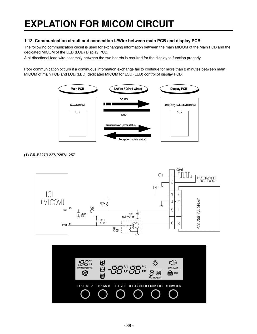
The following communication circuit is used for exchanging information between the main MICOM of the Main PCB and the dedicated MICOM of the LED (LCD) Display PCB.

A bi-directional lead wire assembly between the two boards is required for the display to function properly.

Poor communication occurs if a continuous information exchange fail to continue for more than 2 minutes between main MICOM of main PCB and LCD (LED) dedicated MICOM for LCD (LED) control of display PCB.

Main PCB

Main MICOM

L/Wire FD/H(4-wires)

DC 12V

GND

Transmission (error status)

Display PCB

LCD(LED) dedicated MICOM
Reception (notch status)

(1)GR-P227/L227/P257/L257

- 38 -

Page 40
Image 40
LG Electronics Explation For Micom Circuit, GR-P227/L227/P257/L257, Main PCB, L/Wire FD/H4-wires, Display PCB