Manuals
/
LG Electronics
/
Kitchen Appliance
/
Refrigerator
LG Electronics
GR-P227/L227, GR-P257/L257
service manual
Circuit
Models:
GR-P257/L257
GR-P227/L227
1
46
99
99
Download
99 pages
61.41 Kb
43
44
45
46
47
48
49
50
Troubleshooting
Specs
Install
Door Alarm Buzzer Mute Mode
Faults
Stage Items Indicator Remarks
Problems Causes
Reset circuit
Assembly
Filter Cleaning
Page 46
Image 46
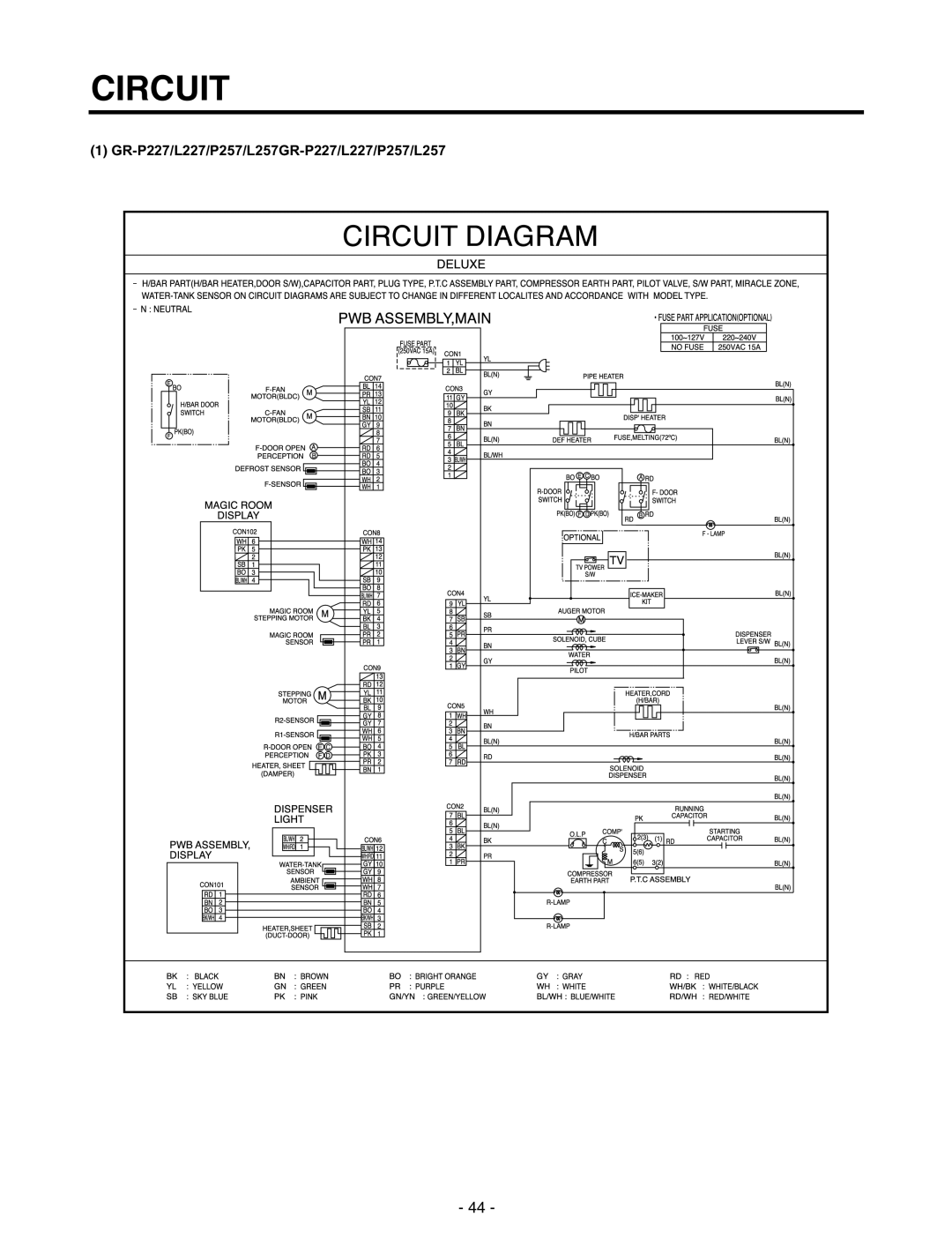
CIRCUIT
(1)
GR-P227/L227/P257/L257GR-P227/L227/P257/L257
- 44 -
Page 45
Page 47
Page 46
Image 46
Page 45
Page 47
Contents
Refrigerator
Contents
Page
Specifications
Front View
Ref No. GR-L227
Ref No. GR-P257
Ref No. GR-L257
Parts Identification
Freezer Refrigerator compartment compartment
Ref No. GR-P227/GR-P257EXTERNAL Filter
Parts Identification
Parts Identification
HOW to Install Refrigerator
How to Adjust Door Height of Refrigerator
Before Installation
How to Install Water Pipe
Class Shape and Spec Nomenclature
Two Hands Type Faucet
Connection of Pipe Connector a and B
Single Lever Type Faucet general
General Type
Filter Cleaning
When customer uses bottled water
Outternal Filter Filter Fixation
After installing water filter
Replacement of water filter
How to Control the Amount of Water Supplied to Icemaker
Confirm the amount of water supplied to the icemaker
Micom Function
Door Alarm Buzzer Mute Mode
Display Power saving Mode
Monitor Panel
Exhibition Mode
Description of Function
Lock function display button lock
Outside temperature display function
LCD Back Light Control
Filter condition display function
Automatic ice maker
When ice maker does not operate smoothly
Dispenser use selection
Express Freezer
Miracle Zone function
Super freezing
Control of variable type of freezing room fan
Doors of freezing
Door opening alarm
Control of M/C room fan motor
Or home bar
Sequential operation of built-in product
Failure Diagnosis Function
Mode Operation Contents Remarks
Test Function
Test Mode 1 Status LCD Test Mode 2 Status LCD
Function of dispenser and water dispenser built-in
Explanation for PWB circuit
Power circuit
Explation for Micom Circuit
GR-P227/L227
Oscillation circuit
Reset circuit
GR-P227/L227/P257/L257
Load/dispenser operation, door opening circuit
Load Driving Circuit
Lever Switch sensing circuit Measuring part
Dispenser operation circuit
Door opening sensing circuit
Temperature sensing circuit
Short Open
Option designation circuit model separation function
Switch entry circuit
Separation Connection Status Application Standard
Stepping motor operation circuit
Fan motor driving circuit freezer, mechanical area
+5 C +9F
33 k Ω 56 k Ω
JCR1
Main PCB
Sensor resistance characteristics table
Miracle Zone Stepping Motor / Display
Operation Principle
Fill/Park Position
Harvest Mode
Icemaking Mode
Water supply amount Table
Stage Items Indicator Remarks
Defect diagnosis function
Circuit
Trouble Shooting
Trouble Diagnosis
Not performed Evaporator by heating as
Refrigeration
Refrigeration Residual
Refrigeration No cooling air circulation Is weak
Fan does not work
Recess
Sounds Compressor compartment operating sounds
Bad soldering Bad rivet contact Short
Structure Door foam Appearance Sag
Problems Causes Checks Measures Remarks
Faults
Power
Problems Causes Checks Measures
Temperature
Cooling
Disconnected from the motor Refer to fan motor disassembly
Defrosting failure
Problems Causes
Measures Remarks
Remove the parts and replace it
Icing
Discharging port of cooling air
Sound
Click Contraction of evaporator Sources
Sound Burping It happens when refrigerant expands
Odor
Problems Symptom Causes Checks Measures Remarks
Micom
Driving circuits
Motor damper
Replace door switch
Trouble Diagnosis
Cooling Cycle Heavy Repair
Items Unit Standards Purposes Remarks
Process Contents Tools
Summary Of Heavy Repair
Precautions During Heavy Repair
Items Precautions
Practical Work For Heavy Repair
When replacing a drier
When replacing a compressor
Inserting a capillary tube
Charging sequence
Pipe Connection
Vacuum Sequence
Calculation of amount of refrigerant charged
Standard Regulations For Heavy Repair
12-0mm
Asia / Middle-East Africa
Brazing Reference Drawings
Europe & CIS / America
Sound depends on the installation location
Problems Checks and Measures
Explain the principles of temperature change
Explain general principles of sounds
Explain the characteriistics of moving parts
Explain the procedure and principles of ice maker operation
Explain the flow of refrigerant
Explain the principles of water supplied to dispenser
Measures for Symptoms on Temperature
Explain the basic principles of food odor
Check the temperature control button and set at strong
Odor and Frost
Explain the basic principles of frost formation
Others
HOW to Disassemble and Assemble
Remove a freezer door
Handle
InsertTubeLineColletClip
Assembly
COVER, Dispenser
Exploded View
Ref No. GR-P227/GR-P257
Optional part
Ref No. GR-L227/GR-L257
Freezer Compartment
Refrigerator Compartment
Optional part
Machine Compartment
ICE & Water Part
Dispenser Part
No JD8999A
Top
Page
Image
Contents