| INSTALLATION |
|
|
|
|
|
|
|
|
|
| ||||||||||
|
|
|
|
|
|
|
|
|
|
|
|
|
|
|
|
|
|
|
|
| |
WIRE DRIVE GEAR RATIO SETTING |
|
|
|
|
|
|
|
|
| ||||||||||||
|
|
|
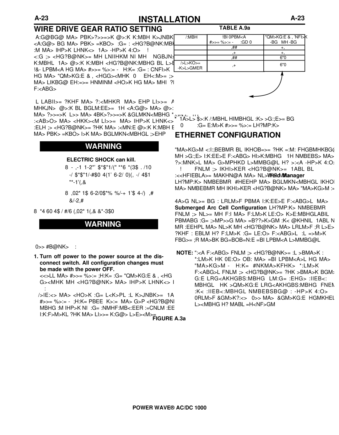
| TABLE A.9a |
|
| |||||||||||||||
|
|
|
|
|
|
|
|
|
|
|
|
|
|
|
| ||||||
Changing the wirefeeder gear ratio requires a gear |
|
|
|
|
|
|
|
|
|
| |||||||||||
Ratio |
|
| Dip Switch #8 | External I/O Jumper | |||||||||||||||||
change in the wire drive, and a configuration change |
|
|
| (Feed Head PCB - Bank S1) | (Pin 5 to Pin 12) | ||||||||||||||||
142:1 |
|
|
|
|
|
|
| OFF |
|
| NO | ||||||||||
at the power source. The Power Wave AC/DC 1000 |
|
|
|
|
|
|
|
|
| ||||||||||||
95:1 |
|
|
|
|
|
|
| ON |
|
| NO | ||||||||||
can be configured to support up to 4 unique gear |
|
|
|
|
|
|
|
|
| ||||||||||||
57:1* |
|
|
|
|
|
|
| OFF |
|
| YES |
| |||||||||
ratios. The gear ratio configuration is selected via a | Reserved* |
|
|
|
|
| ON |
|
| YES | |||||||||||
DIP switch on the Feed Head PC Board and a jumper | (Presently57:1) |
|
|
|
|
|
|
| |||||||||||||
|
|
|
|
|
|
|
|
|
|
|
|
| |||||||||
on the External I/O connector (S7 - located beneath |
|
|
|
|
|
| JUMPER | PIN 5 |
|
| |||||||||||
JUMPER PIN 12 |
|
|
| ||||||||||||||||||
the spring loaded output cover on the top, front of the |
|
|
|
|
|
|
|
|
|
| |||||||||||
|
|
|
|
|
|
|
|
|
|
|
|
|
|
|
| ||||||
machine). |
|
|
|
|
|
|
|
|
|
|
|
|
|
|
|
|
|
| |||
As shipped from the factory, the low speed (high | 12 11 10 9 | 8 | 7 | 6 | 5 | 4 | 3 | 2 | 1 |
|
|
| |||||||||
|
|
|
|
|
|
|
|
|
|
|
|
|
|
|
| ||||||
torque) gear is installed. To change the gear ratio of |
|
|
|
|
|
|
|
|
|
|
|
|
|
|
|
| |||||
the feeder, see the Wirefeeder Instruction Manual. To | * These Gear Ratios options are enabled in | ||||||||||||||||||||
achieve the correct speed, the power source must | |||||||||||||||||||||
also be configured for the actual gear ratio installed in | |||||||||||||||||||||
ETHERNET CONFIGURATION | |||||||||||||||||||||
the wire drive per the instructions below: | |||||||||||||||||||||
|
|
| WARNING | Ethernet capability is provided for data monitoring, or | |||||||||||||||||
|
|
|
|
| |||||||||||||||||
|
|
| ELECTRIC SHOCK can kill. | to enable parallel machine operation. To utilize these | |||||||||||||||||
|
|
| features the network settings of each Power Wave | ||||||||||||||||||
|
|
| • Do not touch electrically live parts | ||||||||||||||||||
|
|
| AC/DC 1000 must be properly configured. This is | ||||||||||||||||||
|
|
| or electrodes with your skin or wet | ||||||||||||||||||
|
|
| accomplished through the use of the Weld Manager | ||||||||||||||||||
|
|
| clothing. | software utility. Follow the instructions provided with | |||||||||||||||||
|
|
| • Insulate yourself from the work and | the utility to properly configure the Ethernet address. | |||||||||||||||||
|
|
|
|
|
|
|
|
|
|
|
|
|
|
|
|
|
|
| |||
|
|
| ground. | When used in a system with parallel machines, the | |||||||||||||||||
• Always wear dry insulating gloves. | Submerged Arc Cell Configuration software utility | ||||||||||||||||||||
must be used to map the master/slave relationships | |||||||||||||||||||||
|
|
|
|
| |||||||||||||||||
|
|
|
|
| within and between the different arc groups. This utili- | ||||||||||||||||
|
|
| WARNING |
| |||||||||||||||||
|
|
|
| ty allows the user to configure the system by selecting | |||||||||||||||||
from a list of master and slave machines (as deter- | ||
mined by their individual dip switch settings). | ||
| ||
(See Figure A.3a) | NOTE: Each machine must be configured as either a | |
1. Turn off power to the power source at the dis- | ||
Master or Slave via the dip switches on the | ||
connect switch. All configuration changes must | ||
Ethernet PC Board. Furthermore, Master | ||
be made with the power OFF. | ||
machines must be configured for either inter- | ||
2. Access the Feed Head board and External I/O con- | ||
nal synchronization (stand alone applica- | ||
nector to configure the power source per table | ||
tions), or external synchronization (multiple | ||
A.9a. | ||
arc applications utilizing a Power Wave | ||
3. Replace the cover and screws as required. The | ||
System Interface). See the "Internal Controls" | ||
Feed Head PC board will "read" the new configura- | ||
section of this document. | ||
tion at power up, and automatically adjust all control | ||
|
parameters for the speed range selected.
FIGURE A.3a
S1EXTERNAL I/O
CONNECTOR
FEEDHEAD
P.C. BOARD
POWER WAVE® AC/DC 1000