| INSTALLATION | ||
|
|
|
|
|
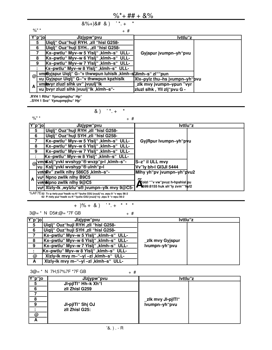
| CONTROL BOARD DIP SWITCH (S1): |
|
BANK S1 | TABLE A.10 |
| |
Switch | Description |
| Comments |
|
| ||
| 1 | Object Instance LSB* (see table A.14) |
|
|
|
| |
| 2 | Object Instance MSB** (see table A.14) |
| (*DEFAULT SETTINGS SHOWN) | |||
| 3 | Equipment Group 1 Select (default | OFF) | Arclink configuration | |||
|
|
|
| ||||
| 4 | Equipment Group 2 Select (default | OFF) |
| O 1 | 2 3 4 5 6 | 7 8 |
|
| N |
|
| |||
| 5 | Equipment Group 3 Select (default | OFF) |
|
|
| |
|
| { |
| ||||
| 6 | Equipment Group 4 Select (default | OFF) |
|
|
| WORK VOLTAGE |
| off | Arclink Object Auto mapping enabled (default) | Default setting | OBJECT INSTANCE | SENSE ENABLE | ||
7 |
|
|
|
|
| ||
on Arclink Object Auto mapping disabled | Requires manual configuration |
| AUTO MAP | ||||
GROUP SELECT |
| ||||||
8 | off | Work sense lead not connected |
| Used for configuring work |
|
|
|
| on Work sense lead connected (default) | sense lead ( See section A ) |
|
|
| ||
*LSB - Least Significant Bit |
|
|
|
|
| ||
**MSB - Most Significant Bit |
|
|
|
|
| ||
FEED HEAD BOARD DIP SWITCH (S1):
BANK S1 |
| TABLE A.11 |
|
|
|
|
|
|
|
|
| |||||||||
|
|
|
|
|
|
|
|
|
|
|
|
|
|
|
|
|
|
| ||
Switch | Description |
|
|
|
| Comments | ||||||||||||||
|
| 1 | Object Instance LSB (see table A.14) |
|
|
|
|
|
|
|
|
|
|
|
|
|
|
| ||
|
|
|
|
|
|
|
|
|
|
|
|
|
|
|
|
| ||||
|
| 2 | Object Instance MSB (see table A.14) |
|
|
|
|
|
| (*DEFAULT SETTINGS SHOWN) | ||||||||||
|
| 3 | Equipment Group 1 Select (default | OFF) |
|
|
| ArcLink Configuration |
|
| 1 |
| 2 |
| 3 |
| 4 | 5 6 7 8 | ||
|
| 4 | Equipment Group 2 Select (default | OFF) |
|
|
|
|
|
| O |
|
|
| ||||||
|
|
|
|
|
|
|
|
|
|
|
|
|
|
|
| |||||
|
|
|
|
|
|
|
|
|
|
|
| N |
|
|
|
|
|
|
|
|
|
| 5 | Equipment Group 3 Select (default | OFF) |
|
|
|
|
|
|
|
|
|
|
|
|
|
| ||
|
|
|
|
|
|
|
| { |
|
|
|
|
| |||||||
|
| 6 | Equipment Group 4 Select (default | OFF) |
|
|
|
|
|
|
|
|
|
|
|
|
|
|
| |
7 |
| off | Electrode polarity positive (default) |
|
|
| Must be OFF for |
|
| OBJECT INSTANCE ELECTRODE | ||||||||||
|
|
|
|
|
|
|
|
|
|
|
|
|
|
|
|
|
|
|
| SPEED RANGE |
|
|
|
|
|
|
|
| Power Wave AC/DC 1000 |
|
|
|
|
|
|
|
|
| |||
|
|
| on | Electrode polarity negative |
|
|
|
|
|
|
|
|
|
| POLARITY | |||||
|
|
| off1 | Low speed gear 142:1 (default) |
|
|
| Gear ratio configuration. |
| GROUP SELECT | ||||||||||
8 |
| on1 | High speed gear 95:1 |
|
|
|
|
|
|
|
|
|
|
|
|
|
|
|
| |
|
|
|
|
|
|
|
|
|
|
|
|
|
|
|
| |||||
| off2 | High speed gear 57:1 |
|
|
| } | These two options available in |
|
|
|
|
|
|
|
|
|
| |||
|
|
|
|
|
|
|
|
|
|
|
|
|
|
|
| |||||
|
|
|
|
|
|
|
|
|
|
|
|
|
|
|
|
| ||||
|
|
| on2 | Reserved (presently configured for 57:1) |
|
|
|
|
|
|
|
|
|
|
| |||||
Notes: 1. No jumper installed on External I/O connector (pin 5 to pin 12). 2. Jumper installed on External I/O connector (pin 5 to pin 12).
ETHERNET BOARD DIP SWITCHES (S1, S2):
| Bank S1 – ArcLink |
|
| TABLE A.12 | |||
|
|
|
|
|
|
|
|
| Switch | Description |
|
|
|
|
|
| 1 | Object Instance LSB (see table A.14) |
|
|
| ||
| 2 | Object Instance MSB (see table A.14) |
|
|
| ||
| 3 | Equipment Group 1 Select (default | OFF) |
|
|
| |
| 4 | Equipment Group 2 Select (default | OFF) |
|
| Used for Arclink | |
| 5 | Equipment Group 3 Select (default | OFF) |
|
| Configuration | |
| 6 | Equipment Group 4 Select (default | OFF) |
|
|
| |
| 7 | Reserved for future use (default | OFF) |
|
|
| |
| 8 | Reserved for future use (default | OFF) |
|
|
| |
|
|
|
|
|
|
|
|
| Bank S2 – DeviceNet |
|
| TABLE A.13 | |||
Comments
(*DEF AULTES NHIST SG WO N)
O | 421 |
| 3 |
|
|
| 5 |
| 6 |
|
|
| 7 |
| 8 |
|
N |
|
|
|
|
|
|
|
|
|
|
|
|
|
|
|
|
|
|
|
|
|
|
|
|
|
|
|
|
|
|
|
|
|
{ |
|
|
|
|
|
|
|
| { |
| ||||||
EOBJ NI T TSNA CE |
| RERES |
| EV D | ||||||||||||
| PGROU LES |
|
| ECT |
|
|
|
|
| |||||||
Switch
1
2
3
4
5
6
7
8
Description
DeviceNet Baud Rate see Table A.15
DeviceNet Mac ID see Table A.16
Comments |
|
|
| |
| (*DEFAULT SETTINGS SHOWN) | |||
| O 1 2 3 4 | 5 6 | 7 | 8 |
Used for DeviceNet | N |
|
|
|
{ |
|
|
| |
Configuration |
|
|
| |
|
|
|
| |
| BAUD RATE (125K) |
|
|
|
| DEVICENET MAC ID (62) | |||
POWER WAVE® AC/DC 1000