Lincoln Electric SVM133-B service manual Pos

Models: SVM133-B

1 197
Download 197 pages 45.78 Kb
Page 176
Image 176

Return to Section TOC

Return to Section TOC

Return to Section TOC

Return to Section TOC

Return to Master TOC

Return to Master TOC

Return to Master TOC

Return to Master TOC

G-4

ELECTRICAL DIAGRAMS

G-4

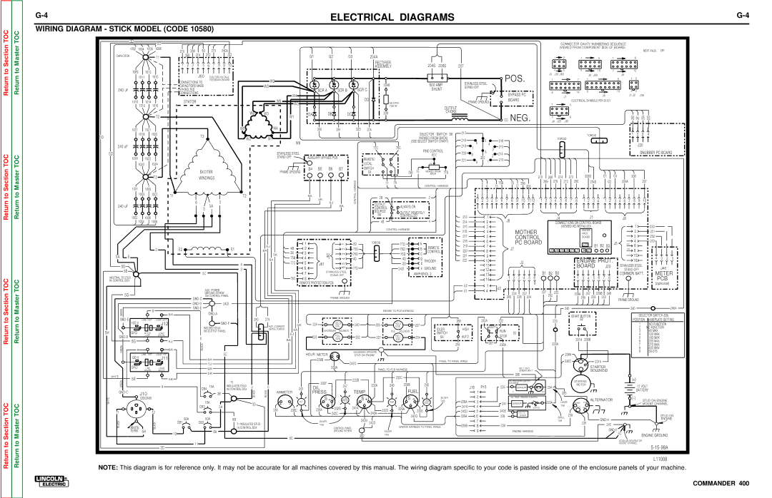
WIRING DIAGRAM - STICK MODEL (CODE 10580)


3D


5D


CONNECTOR CAVITY NUMBERING SEQUENCE


1002

1004

1006

1008


268


5D

273


240A


(VIEWED FROM COMPONENT SIDE OF BOARD)


NEXT AVLB.

287


270


CAPACITOR


T1


269


274

272


3D


G1

G2

G3


204A


1

3


1


5


1


6


1

2

3

4

5

6

7

8

9

10


RECTIFIER


204S

206S


207


ASSEMBLY


4

6


6


1009

1013


10


7


12


J50


POS.


J3

,J31,J60


J6

,J50


J8


1011


1015


EXCITER VOLTAGE


1


7


1


8


1

2


CONNECTIONS TO

FEEDBACK BOARD


W2


204B


600 AMP


STAINLESS STEEL


CAPACITORS MADE


W5


240 uF


SCR A


SCR B

SCR C


STAND-OFF


VIA BOLTED


SHUNT


8


14


9


16


3

4


CONNECTIONS


W4


BYPASS PC


J5


J1,J2

,J30


DD


J7


1010


1014


STATOR


W6

W3


50 Ohm


FRAME GROUND


BOARD


1


ELECTRICAL SYMBOLS PER E1537


1012


1016


100 W


OUTPUT


4


W6

W3


DA


DB

DC


209


CHOKE


NEG.


T2


W1


5


8


260

261

204

223


CC


J4 ,J23

,J61


1017


1021


W5


W4


260


261

223

204


217


1

2

3

4


3D


1019


1023


T3


SELECTOR

SWITCH

S8


TOROID


W2


W1


(VIEWED FROM BACK)


218


5


216


TOROID


W6


(SEE SELECT SWITCH CHART)


6


240 uF


77C


76C


219


4


215


J30


7


3


FINE CONTROL


A


5D


STAINLESS STEEL


220


SNUBBER PC BOARD


8


214


POT


2


1018


1022


STAND-OFF

AUXILIARY BYPASS PCB

REMOTE/


222


221


1


213


9


1020


1024


LOCAL


CW


EXCITER


FRAME GROUND

B4

B5

B6

B7

SWITCH


75


VIEWED FROM


S1


76B


77B


T3


BACK


270


273


206S


G1


G3


206


WINDINGS


268

274


280


HARNESS


77

76


2

4


75B


76


256


269

279

272


204S


G2


204A


207


1001


1005


CONTROL HARNESS


75


77

255


1003


1007

T1


T2


9A


CONTROL


2B


2


5K


2

3


5

6


8

9

10

11 12

1

2


4

6


2


2


9


1

4

7

3

7

8

1

3

4

1

3

4

6

7

8

10


6


3


5J


240 uF


5A


8A


OUTPUT


ALWAYS ON


5


CONTROL


SOURCE


OUTPUT REMOTELY


S6


1002


1006


CONTROLLED


213


1


J4


J1


J6


4


J8


1004


1008


4B


214


2


CONNECTIONS ON CONTROL BOARD


1


CONTROL HARNESS


215


3


(VIEWED AS INSTALLED)


250


216


4


MOTHER


ENGINE


2


251


PROT.


217


5


CONTROL


BOARD


3


252


1


1

2D


TOROID


77D


A


218


6


PC BOARD


J23


J5


4


253


219


B1 B2 B3


SPI


5J

4B


2


REMOTE


7


6


3

E2


E1


8A


2


75D


76D


B


220


8


J7


J2 J6 J5 J8 J7

J1

J4

J3


SCI

8


2B

3


CONTROL


5A

5


5K

J60

4 3

76D


75D


C


221


9


15


75B

4


4

3

2

1


9A

4D


4D


D

TRIGGER


222


ENGINE PROT.


16


77C

5


10


J3


5D


6


J61


2D


E


11


BOARD


J23


STAINLESS STEEL


6


6

77D


242I


F

GROUND


J40


5E


3


12


STAND-OFF


5C


7

STAINLESS STEEL


AMPHENOL 2


13


B1

B2

B3


COMMON BATT.

METER

NEUTRAL T2 STUD


STAND-OFF


6

7


76C

8


14


1

2

3

4

5

6


1

3

4

5

8


PCB


IN CONTROL BOX


REMOTE PROTECTION PCB


E2


1


(optional)


J2


AUX. POWER


E1


4


227


232


5G


GROUND SCREW


224

237


262


239A

247

229B

246


ON CONTROL PANEL


GND-C


FRAME GROUND


285

226

234


245


233

243


FRAME GROUND


GND-D


242I


GREEN


8


GND-E


ENGINE TO PCB HARNESS


240


240


240A


8A


GND-A


START BUTTON


SELECTOR SWITCH (S8)


GND-E

120 V

LINE HOT

LOAD HOT


280

279


256


232A


232


233


S2


POSITION

NAMEPLATE SETTING


J12


GND-F


224

HOLD

240


226


HOLD


1


NO FUNCTION


AUX. CURRENT

5K


237


WELDED STUD


COIL


COIL


IDLER


HIGH


232H


2


NO FUNCTION


SENSE TOROID

9A


5H


GFCI


ON OUTPUT PANEL


SHUTDOWN

SOLENOID


IDLE

SOLENOID


RUN


3


90 MAX


SWITCH


S3


WHITE


LOAD


5J


4


120 MAX


GND-D


LINE


WHITE


225

PULL

262


227


PULL


S4


AUTO


STOP


8


254


5


180 MAX


5G


8A


COIL


COIL


231A

236B


5J


267


6


230 MAX


233A


GREEN


BLACK


255


236A


7


270 MAX


9


9A


8


400 MAX


SOLENOID GROUND


9


50-575


LINE

HOT

LOAD HOT


5C


HOUR METER

+

-


236A


STUD ON ENGINE


120 V


J11


8A


239B


236C


231A


242G


PANEL TO PANEL WIRES


5J


GFCI


STARTER


LINE


LOAD


9A


239A


PANEL TO PCB HARNESS


BOLT ONTO


WHITE


WHITE


SENDER BRK'T


SOLENOID


5K


WHITE


5E


232C


286


5K


232B


(+)


GREEN


T3


232F


OIL PRESSURE SWITCH


STARTING


232A

246

229B


245


& SENSOR


MOTOR


9


CB4 15A


INSULATED STUD

3


6

243


OIL


247


J16

P16


228


SENSOR


234


12 VOLT


IN CONTROL BOX


SWITCH


GND-C


J10


3B


BLACK

BLACK

AMMETER


PRESS.


TEMP.


FUEL


1


G


WK


285


BATTERY


120/240V


S

+

LOW

S

+


S


SILVER


2


OIL TEMP. SENSOR & SWITCH


ALTERNATOR


(-)


STUD ON ENGINE


WHITE


15A


ALT.


-

PRESS.

-


TEMP.

-+


LOW

TAB


228A

3


241


233A

LARGE


EXC


3D


+


SENSOR


MOUNT CHANNEL


-


FUEL


TAB


SENSE


CB3


3A


238

236C


228A

232G

241A


232D


229A


241A

4


SWITCH


POS

NEG


11


12


232E


242D

5


242E


242C


242A


242G


229A

6


229


FUEL LVL.


239


STUD ON


50A


50A


SENSOR


SMALL


BLACK


CB1


CB2


6B


SILVER


242B

242D


7


TAB


238


GND-H


ENGINE


BLACK


T1 INSULATED STUD


TAB


239B

8


239


242


WHITE


ENGINE HARNESS TO PANEL WIRES


6A


IN CONTROL BOX


CONTROL PANEL


GND-F


TERM.

5H


12


GROUND SCREW


SILVER


9


ENGINE HARNESS


5C


ENGINE GROUND


5C


242


TAB


STUD ON GENERATOR


11


MOUNT CHANNEL


5-15-98A


3D


L11008


NOTE: This diagram is for reference only. It may not be accurate for all machines covered by this manual. The wiring diagram specific to your code is pasted inside one of the enclosure panels of your machine.

COMMANDER 400

Page 176
Image 176
Lincoln Electric SVM133-B service manual Pos

SVM133-B specifications

The Lincoln Electric SVM133-B is an innovative welding machine designed to meet the diverse needs of welders and fabrication shops. This versatile equipment combines state-of-the-art technology with user-friendly features, making it ideal for both novice and professional welders.

One of the main features of the SVM133-B is its advanced inverter technology. This allows for a more efficient power delivery, which translates into reduced energy consumption and lower operational costs. The machine is capable of delivering optimal welding performance across a range of materials, from thin sheets to heavier sections, making it suitable for various applications in industries such as automotive, construction, and repair.

The SVM133-B supports multiple welding processes, including MIG, stick, and TIG welding. This flexibility ensures that users can adapt to various job requirements without needing multiple machines. The intuitive control panel allows users to switch between modes effortlessly, providing a seamless welding experience.

Another notable characteristic of the SVM133-B is its compact and lightweight design. Weighing significantly less than traditional welding machines, it is highly portable, making it easy to transport to different job sites. Additionally, its rugged construction ensures durability, allowing it to withstand tough working conditions.

The SVM133-B is equipped with advanced safety features, such as overheat and overload protection, which safeguard both the machine and the user during operation. It also includes a digital display that provides real-time feedback on settings, voltage, and amperage, which enhances precision and control during welding tasks.

Lincoln Electric has prioritized ease of use in the SVM133-B, with quick setup guides and clear instructions. This user-centric approach not only facilitates a smoother learning curve for beginners but also optimizes the workflow for experienced welders, enabling them to maximize productivity.

One of the standout features is the capability to weld aluminum with ease, thanks to its spool gun compatibility. This feature sets the SVM133-B apart from many competitors, providing added value for users who require flexibility in their welding projects.

In summary, the Lincoln Electric SVM133-B stands out in the welding machine market due to its inverter technology, multi-process capabilities, portability, and robust safety measures. It embodies the perfect blend of innovation and practicality, making it a top choice for welders looking to enhance their skills and productivity across a wide array of applications. Whether for professional use or hobbyist projects, the SVM133-B offers a reliable solution for high-quality welding tasks.