Return to Section TOC

Return to Section TOC

Return to Section TOC

Return to Section TOC

Return to Master TOC

Return to Master TOC

Return to Master TOC

Return to Master TOC

G-6

ELECTRICAL DIAGRAMS

G-6

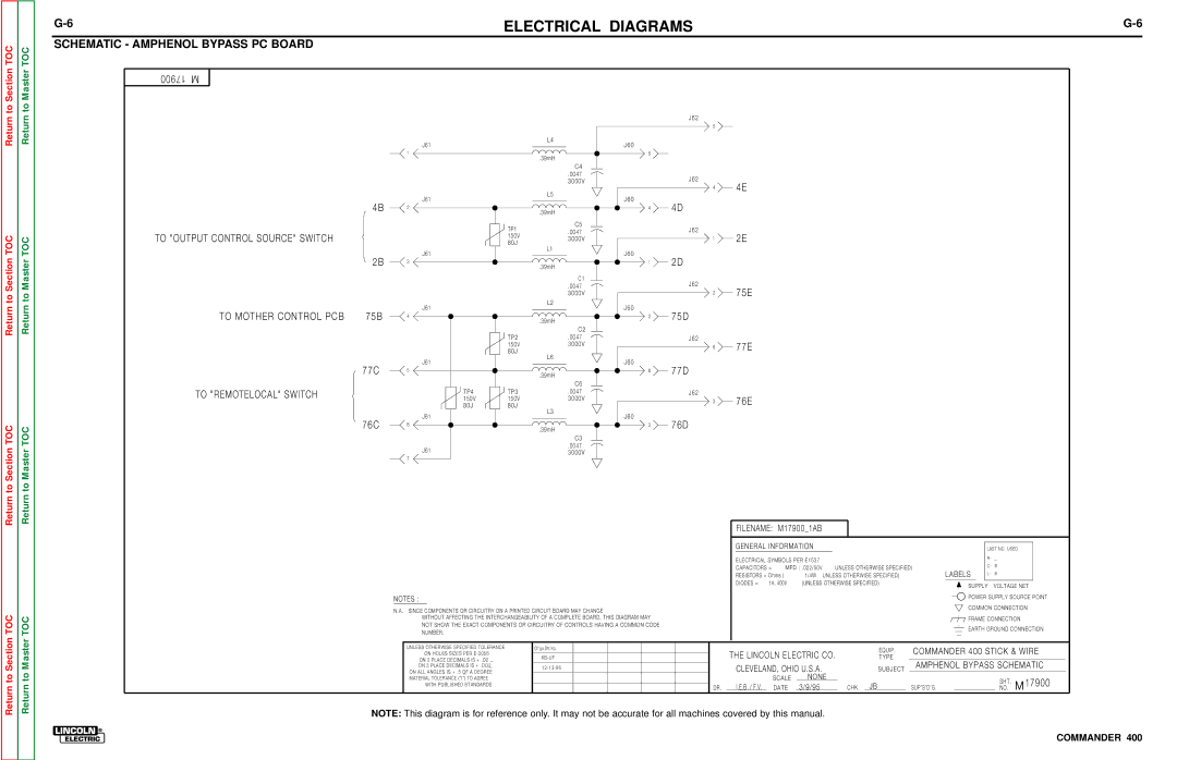
SCHEMATIC - AMPHENOL BYPASS PC BOARD


17900

M


J62


5


J61


L4


J60


1


5


.39mH


C4


.0047

J62


3000V

4E


4


L5


J61


4B


J60

4D


2


4


.39mH


TP1

C5

J62


.0047


TO "OUTPUT CONTROL SOURCE" SWITCH


150V


2E


3000V

1


80J


L1


J61


2B


J60

2D


3


1


.39mH


C1

J62


.0047

75E


3000V

2


J61


L2


TO MOTHER CONTROL PCB

75B


J60

75D


4


2


.39mH


C2


TP2

.0047

J62


150V

3000V

6

77E


80J


L6


J61


77C


J60

77D


5


6


.39mH


C6


TO "REMOTELOCAL" SWITCH


TP4

TP3

.0047

J62


3000V


150V

150V

3

76E


80J

80J


L3


J61


76C


J60

76D


8


3


.39mH


C3


J61


.0047


3000V


7


FILENAME:

M17900_1AB


GENERAL INFORMATION


LAST NO. USED


ELECTRICAL SYMBOLS PER E1537


R- _


CAPACITORS =

MFD ( .022/50V

UNLESS OTHERWISE SPECIFIED)

C- 6


RESISTORS = Ohms (

1/4W

UNLESS OTHERWISE SPECIFIED)

LABELS

L-

6


DIODES =

1A, 400V

(UNLESS OTHERWISE SPECIFIED)

SUPPLY

VOLTAGE NET


NOTES :


POWER SUPPLY SOURCE POINT


N.A. SINCE COMPONENTS OR CIRCUITRY ON A PRINTED CIRCUIT BOARD MAY CHANGE


COMMON CONNECTION


WITHOUT AFFECTING THE INTERCHANGEABILITY OF A COMPLETE BOARD, THIS DIAGRAM MAY


FRAME CONNECTION


NOT SHOW THE EXACT COMPONENTS OR CIRCUITRY OF CONTROLS HAVING A COMMON CODE


EARTH GROUND CONNECTION


NUMBER.


UNLESS OTHERWISE SPECIFIED TOLERANCE


Ch’ge.Sht.No.


THE LINCOLN ELECTRIC CO.

EQUIP.

COMMANDER 400 STICK & WIRE


ON HOLES SIZES PER E-2056


XB-UF


ON 2 PLACE DECIMALS IS + .O2


TYPE

AMPHENOL BYPASS SCHEMATIC


ON 3 PLACE DECIMALS IS + .OO2


12-13-96


CLEVELAND, OHIO U.S.A.


SUBJECT


ON ALL ANGLES IS + .5 OF A DEGREE


MATERIAL TOLERANCE ("t") TO AGREE


SCALE

NONE


SHT.

M 17900


WITH PUBLISHED STANDARDS


I.E.B. / F.V.


3/9/95

CHK.

JB

SUP’S’D’G.


DR.


DATE


NO.

NOTE: This diagram is for reference only. It may not be accurate for all machines covered by this manual.

COMMANDER 400

Page 178
Image 178
Lincoln Electric SVM133-B service manual Schematic Amphenol Bypass PC Board, To Mother Control PCB

SVM133-B specifications

The Lincoln Electric SVM133-B is an innovative welding machine designed to meet the diverse needs of welders and fabrication shops. This versatile equipment combines state-of-the-art technology with user-friendly features, making it ideal for both novice and professional welders.

One of the main features of the SVM133-B is its advanced inverter technology. This allows for a more efficient power delivery, which translates into reduced energy consumption and lower operational costs. The machine is capable of delivering optimal welding performance across a range of materials, from thin sheets to heavier sections, making it suitable for various applications in industries such as automotive, construction, and repair.

The SVM133-B supports multiple welding processes, including MIG, stick, and TIG welding. This flexibility ensures that users can adapt to various job requirements without needing multiple machines. The intuitive control panel allows users to switch between modes effortlessly, providing a seamless welding experience.

Another notable characteristic of the SVM133-B is its compact and lightweight design. Weighing significantly less than traditional welding machines, it is highly portable, making it easy to transport to different job sites. Additionally, its rugged construction ensures durability, allowing it to withstand tough working conditions.

The SVM133-B is equipped with advanced safety features, such as overheat and overload protection, which safeguard both the machine and the user during operation. It also includes a digital display that provides real-time feedback on settings, voltage, and amperage, which enhances precision and control during welding tasks.

Lincoln Electric has prioritized ease of use in the SVM133-B, with quick setup guides and clear instructions. This user-centric approach not only facilitates a smoother learning curve for beginners but also optimizes the workflow for experienced welders, enabling them to maximize productivity.

One of the standout features is the capability to weld aluminum with ease, thanks to its spool gun compatibility. This feature sets the SVM133-B apart from many competitors, providing added value for users who require flexibility in their welding projects.

In summary, the Lincoln Electric SVM133-B stands out in the welding machine market due to its inverter technology, multi-process capabilities, portability, and robust safety measures. It embodies the perfect blend of innovation and practicality, making it a top choice for welders looking to enhance their skills and productivity across a wide array of applications. Whether for professional use or hobbyist projects, the SVM133-B offers a reliable solution for high-quality welding tasks.