Return to Section TOC

to Section TOC

Return to Master TOC

to Master TOC

F-48

F-48

TROUBLESHOOTING & REPAIR

ACTIVE SCR TEST (continued)

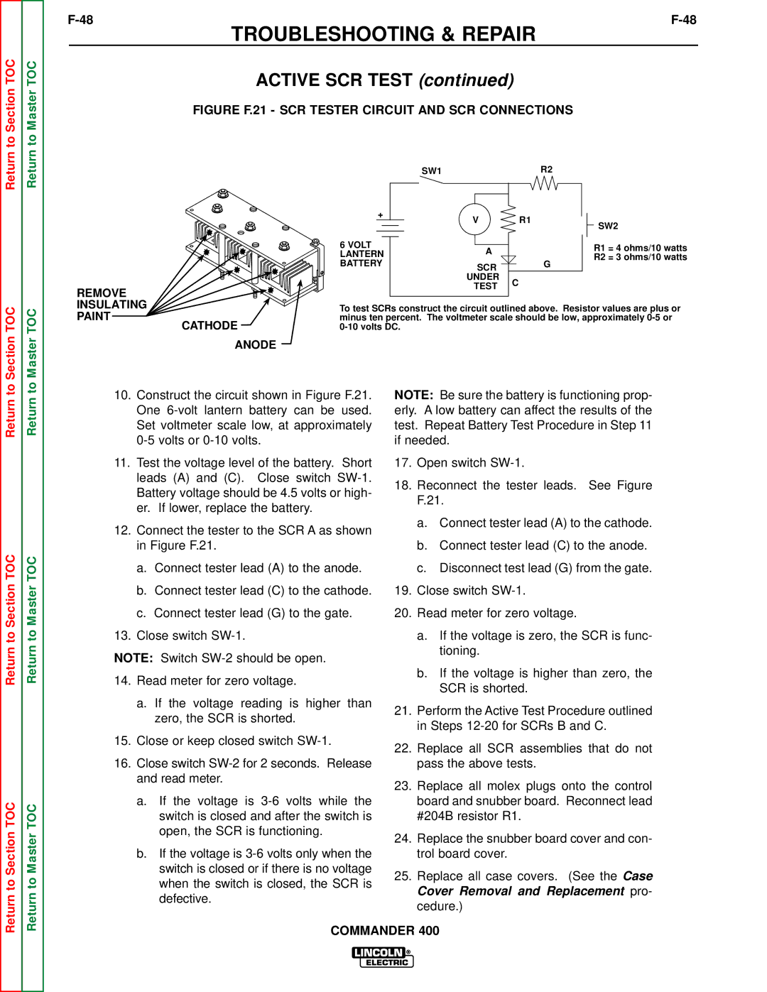
FIGURE F.21 - SCR TESTER CIRCUIT AND SCR CONNECTIONS


SW1


R2


+

V

R1


SW2


6 VOLT

A


R1 = 4 ohms/10 watts


LANTERN


R2 = 3 ohms/10 watts


BATTERY


SCR


G


UNDER

C


REMOVE


TEST


INSULATING

To test SCRs construct the circuit outlined above. Resistor values are plus or

PAINT

minus ten percent. The voltmeter scale should be low, approximately 0-5 or

CATHODE

0-10 volts DC.


ANODE

Return

Return to Section TOC

Return to Section TOC

Return

Return to Master TOC

Return to Master TOC

10.Construct the circuit shown in Figure F.21. One 6-volt lantern battery can be used. Set voltmeter scale low, at approximately 0-5 volts or 0-10 volts.

11.Test the voltage level of the battery. Short leads (A) and (C). Close switch SW-1. Battery voltage should be 4.5 volts or high- er. If lower, replace the battery.

12.Connect the tester to the SCR A as shown in Figure F.21.

a.Connect tester lead (A) to the anode.

b.Connect tester lead (C) to the cathode.

c.Connect tester lead (G) to the gate.

13.Close switch SW-1.

NOTE: Switch SW-2 should be open.

14.Read meter for zero voltage.

a.If the voltage reading is higher than zero, the SCR is shorted.

15.Close or keep closed switch SW-1.

16.Close switch SW-2 for 2 seconds. Release and read meter.

a.If the voltage is 3-6 volts while the switch is closed and after the switch is open, the SCR is functioning.

b.If the voltage is 3-6 volts only when the switch is closed or if there is no voltage when the switch is closed, the SCR is defective.

NOTE: Be sure the battery is functioning prop- erly. A low battery can affect the results of the test. Repeat Battery Test Procedure in Step 11 if needed.

17.Open switch SW-1.

18.Reconnect the tester leads. See Figure F.21.

a.Connect tester lead (A) to the cathode.

b.Connect tester lead (C) to the anode.

c.Disconnect test lead (G) from the gate.

19.Close switch SW-1.

20.Read meter for zero voltage.

a.If the voltage is zero, the SCR is func- tioning.

b.If the voltage is higher than zero, the SCR is shorted.

21.Perform the Active Test Procedure outlined in Steps 12-20 for SCRs B and C.

22.Replace all SCR assemblies that do not pass the above tests.

23.Replace all molex plugs onto the control board and snubber board. Reconnect lead #204B resistor R1.

24.Replace the snubber board cover and con- trol board cover.

25.Replace all case covers. (See the Case Cover Removal and Replacement pro- cedure.)

COMMANDER 400

Page 102
Image 102
Lincoln Electric SVM133-B service manual Figure F.21 SCR Tester Circuit and SCR Connections

SVM133-B specifications

The Lincoln Electric SVM133-B is an innovative welding machine designed to meet the diverse needs of welders and fabrication shops. This versatile equipment combines state-of-the-art technology with user-friendly features, making it ideal for both novice and professional welders.

One of the main features of the SVM133-B is its advanced inverter technology. This allows for a more efficient power delivery, which translates into reduced energy consumption and lower operational costs. The machine is capable of delivering optimal welding performance across a range of materials, from thin sheets to heavier sections, making it suitable for various applications in industries such as automotive, construction, and repair.

The SVM133-B supports multiple welding processes, including MIG, stick, and TIG welding. This flexibility ensures that users can adapt to various job requirements without needing multiple machines. The intuitive control panel allows users to switch between modes effortlessly, providing a seamless welding experience.

Another notable characteristic of the SVM133-B is its compact and lightweight design. Weighing significantly less than traditional welding machines, it is highly portable, making it easy to transport to different job sites. Additionally, its rugged construction ensures durability, allowing it to withstand tough working conditions.

The SVM133-B is equipped with advanced safety features, such as overheat and overload protection, which safeguard both the machine and the user during operation. It also includes a digital display that provides real-time feedback on settings, voltage, and amperage, which enhances precision and control during welding tasks.

Lincoln Electric has prioritized ease of use in the SVM133-B, with quick setup guides and clear instructions. This user-centric approach not only facilitates a smoother learning curve for beginners but also optimizes the workflow for experienced welders, enabling them to maximize productivity.

One of the standout features is the capability to weld aluminum with ease, thanks to its spool gun compatibility. This feature sets the SVM133-B apart from many competitors, providing added value for users who require flexibility in their welding projects.

In summary, the Lincoln Electric SVM133-B stands out in the welding machine market due to its inverter technology, multi-process capabilities, portability, and robust safety measures. It embodies the perfect blend of innovation and practicality, making it a top choice for welders looking to enhance their skills and productivity across a wide array of applications. Whether for professional use or hobbyist projects, the SVM133-B offers a reliable solution for high-quality welding tasks.