Return to Section TOC

TOC

Return to Master TOC

TOC

F-34

F-34

TROUBLESHOOTING & REPAIR

IDLER SOLENOID TEST (continued)

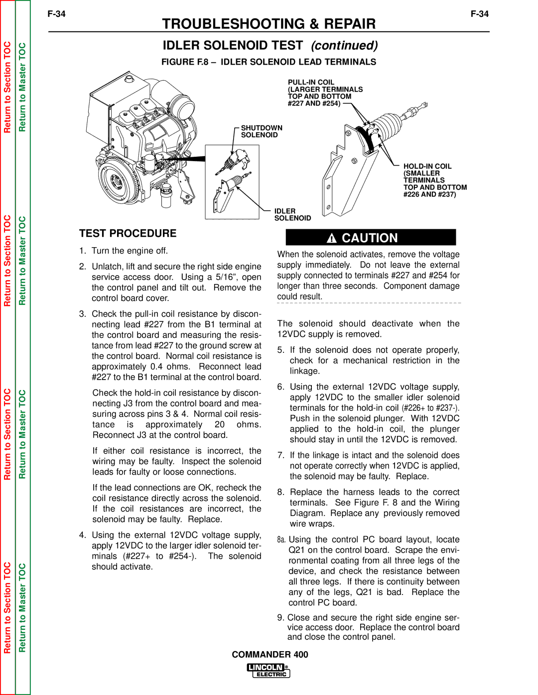
FIGURE F.8 – IDLER SOLENOID LEAD TERMINALS

PULL-IN COIL (LARGER TERMINALS TOP AND BOTTOM #227 AND #254)

SHUTDOWN

SOLENOID

HOLD-IN COIL (SMALLER TERMINALS

TOP AND BOTTOM #226 AND #237)

IDLER

SOLENOID

Return to Section

Return to Section TOC

Return to Section TOC

Return to Master

Return to Master TOC

Return to Master TOC

TEST PROCEDURE

1.Turn the engine off.

2.Unlatch, lift and secure the right side engine service access door. Using a 5/16”, open the control panel and tilt out. Remove the control board cover.

3.Check the pull-in coil resistance by discon- necting lead #227 from the B1 terminal at the control board and measuring the resis- tance from lead #227 to the ground screw at the control board. Normal coil resistance is approximately 0.4 ohms. Reconnect lead #227 to the B1 terminal at the control board.

Check the hold-in coil resistance by discon- necting J3 from the control board and mea- suring across pins 3 & 4. Normal coil resis- tance is approximately 20 ohms. Reconnect J3 at the control board.

If either coil resistance is incorrect, the wiring may be faulty. Inspect the solenoid leads for faulty or loose connections.

If the lead connections are OK, recheck the coil resistance directly across the solenoid. If the coil resistances are incorrect, the solenoid may be faulty. Replace.

4.Using the external 12VDC voltage supply, apply 12VDC to the larger idler solenoid ter- minals (#227+ to #254-). The solenoid should activate.

CAUTION

When the solenoid activates, remove the voltage supply immediately. Do not leave the external supply connected to terminals #227 and #254 for longer than three seconds. Component damage could result.

The solenoid should deactivate when the 12VDC supply is removed.

5.If the solenoid does not operate properly, check for a mechanical restriction in the linkage.

6.Using the external 12VDC voltage supply, apply 12VDC to the smaller idler solenoid terminals for the hold-in coil (#226+ to #237-). Push in the solenoid plunger. With 12VDC applied to the hold-in coil, the plunger should stay in until the 12VDC is removed.

7.If the linkage is intact and the solenoid does not operate correctly when 12VDC is applied, the solenoid may be faulty. Replace.

8.Replace the harness leads to the correct terminals. See Figure F. 8 and the Wiring Diagram. Replace any previously removed wire wraps.

8a. Using the control PC board layout, locate

Q21 on the control board. Scrape the envi- ronmental coating from all three legs of the device, and check the resistance between all three legs. If there is continuity between any of the legs, Q21 is bad. Replace the control PC board.

9.Close and secure the right side engine ser- vice access door. Replace the control board and close the control panel.

COMMANDER 400

Page 88
Image 88
Lincoln Electric SVM133-B service manual Idler Solenoid Test, Test Procedure

SVM133-B specifications

The Lincoln Electric SVM133-B is an innovative welding machine designed to meet the diverse needs of welders and fabrication shops. This versatile equipment combines state-of-the-art technology with user-friendly features, making it ideal for both novice and professional welders.

One of the main features of the SVM133-B is its advanced inverter technology. This allows for a more efficient power delivery, which translates into reduced energy consumption and lower operational costs. The machine is capable of delivering optimal welding performance across a range of materials, from thin sheets to heavier sections, making it suitable for various applications in industries such as automotive, construction, and repair.

The SVM133-B supports multiple welding processes, including MIG, stick, and TIG welding. This flexibility ensures that users can adapt to various job requirements without needing multiple machines. The intuitive control panel allows users to switch between modes effortlessly, providing a seamless welding experience.

Another notable characteristic of the SVM133-B is its compact and lightweight design. Weighing significantly less than traditional welding machines, it is highly portable, making it easy to transport to different job sites. Additionally, its rugged construction ensures durability, allowing it to withstand tough working conditions.

The SVM133-B is equipped with advanced safety features, such as overheat and overload protection, which safeguard both the machine and the user during operation. It also includes a digital display that provides real-time feedback on settings, voltage, and amperage, which enhances precision and control during welding tasks.

Lincoln Electric has prioritized ease of use in the SVM133-B, with quick setup guides and clear instructions. This user-centric approach not only facilitates a smoother learning curve for beginners but also optimizes the workflow for experienced welders, enabling them to maximize productivity.

One of the standout features is the capability to weld aluminum with ease, thanks to its spool gun compatibility. This feature sets the SVM133-B apart from many competitors, providing added value for users who require flexibility in their welding projects.

In summary, the Lincoln Electric SVM133-B stands out in the welding machine market due to its inverter technology, multi-process capabilities, portability, and robust safety measures. It embodies the perfect blend of innovation and practicality, making it a top choice for welders looking to enhance their skills and productivity across a wide array of applications. Whether for professional use or hobbyist projects, the SVM133-B offers a reliable solution for high-quality welding tasks.