OPERATION | ||
|
CONTROLS AND SETTINGS
Return to Master TOC
Return to Master TOC
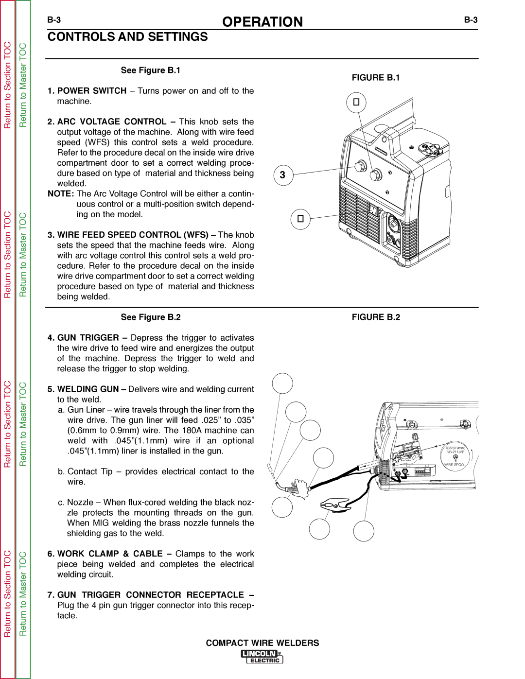
See Figure B.1
1.POWER SWITCH – Turns power on and off to the machine.
2.ARC VOLTAGE CONTROL – This knob sets the output voltage of the machine. Along with wire feed speed (WFS) this control sets a weld procedure. Refer to the procedure decal on the inside wire drive compartment door to set a correct welding proce-
dure based on type of material and thickness being | 3 |
welded. |
|
NOTE: The Arc Voltage Control will be either a contin- |
|
uous control or a |
|
ing on the model. | 1 |
|
3.WIRE FEED SPEED CONTROL (WFS) – The knob sets the speed that the machine feeds wire. Along with arc voltage control this control sets a weld pro- cedure. Refer to the procedure decal on the inside wire drive compartment door to set a correct welding procedure based on type of material and thickness being welded.
FIGURE B.1
2
See Figure B.2 | FIGURE B.2 |
Return to Section TOC
Return to Section TOC
Return to Section TOC
Return to Section TOC
Return to Master TOC
Return to Master TOC
4.GUN TRIGGER – Depress the trigger to activates the wire drive to feed wire and energizes the output of the machine. Depress the trigger to weld and release the trigger to stop welding.
5.WELDING GUN – Delivers wire and welding current to the weld.
a.Gun Liner – wire travels through the liner from the wire drive. The gun liner will feed .025” to .035” (0.6mm to 0.9mm) wire. The 180A machine can weld with .045”(1.1mm) wire if an optional
.045”(1.1mm) liner is installed in the gun.
b.Contact Tip – provides electrical contact to the wire.
c.Nozzle – When
6.WORK CLAMP & CABLE – Clamps to the work piece being welded and completes the electrical welding circuit.
7.GUN TRIGGER CONNECTOR RECEPTACLE – Plug the 4 pin gun trigger connector into this recep- tacle.
5c
5b
5a
.035"(0.9mm)
5
WIRE SPOOL
4
6 7
COMPACT WIRE WELDERS