Return to Section TOC
Return to Section TOC
Return to Section TOC
Return to Section TOC
Return to Master TOC
Return to Master TOC
Return to Master TOC
Return to Master TOC
TROUBLESHOOTING & REPAIR | ||
|
FAN MOTOR ASSEMBLY REMOVAL AND REPLACEMENT PROCEDURE
(CONTINUED)
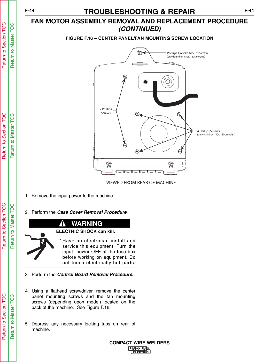
FIGURE F.16 – CENTER PANEL/FAN MOUNTING SCREW LOCATION
![]()
![]() Phillips Handle Mount Screw
Phillips Handle Mount Screw
(only found on 140c/180c models)
2 Phillips
Screws
4 Phillips Screws
(only found on 140c/180c models)
VIEWED FROM REAR OF MACHINE
1.Remove the input power to the machine.
2.Perform the Case Cover Removal Procedure.
WARNING
ELECTRIC SHOCK can kill.
•Have an electrician install and service this equipment. Turn the input power OFF at the fuse box before working on equipment. Do
not touch electrically hot parts.
3.Perform the Control Board Removal Procedure.
4.Using a flathead screwdriver, remove the center panel mounting screws and the fan mounting screws (depending upon model) located on the back of the machine. See Figure F.16.
5.Depress any necessary locking tabs on rear of machine.