Return to Section TOC
Return to Master TOC
OPERATION | ||
| ||
|
|
|
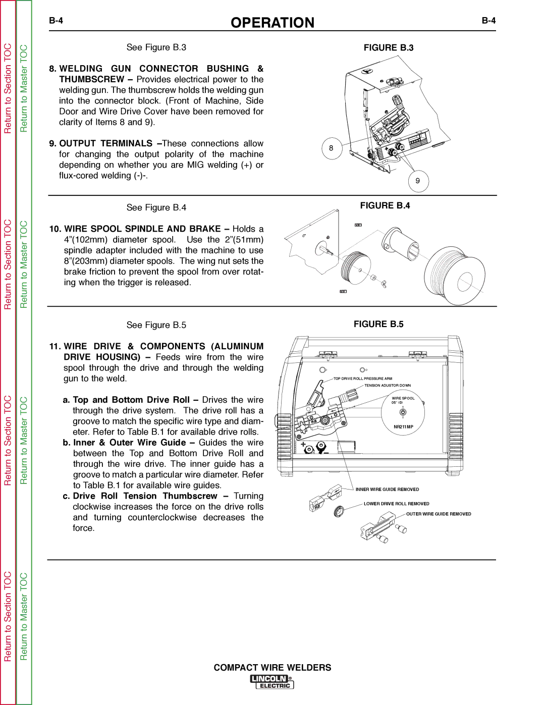
See Figure B.3 |
| FIGURE B.3 |
8. WELDING GUN CONNECTOR BUSHING & THUMBSCREW – Provides electrical power to the welding gun. The thumbscrew holds the welding gun into the connector block. (Front of Machine, Side Door and Wire Drive Cover have been removed for clarity of Items 8 and 9).
9. OUTPUT TERMINALS | 8 | |
for changing the output polarity of the machine | ||
| ||
depending on whether you are MIG welding (+) or |
| |
9 | ||
|
Return to Section TOC
Return to Master TOC
See Figure B.4
10.WIRE SPOOL SPINDLE AND BRAKE – Holds a 4”(102mm) diameter spool. Use the 2”(51mm) spindle adapter included with the machine to use 8”(203mm) diameter spools. The wing nut sets the brake friction to prevent the spool from over rotat- ing when the trigger is released.
FIGURE B.4
2"(51mm) SPINDLE ADAPTER (FOR 8"(20mm) REEL OF WIRE)
( 4"(102mm) REEL OF WIRE)
Return to Section TOC
Return to Master TOC
See Figure B.5
11.WIRE DRIVE & COMPONENTS (ALUMINUM DRIVE HOUSING) – Feeds wire from the wire spool through the drive and through the welding gun to the weld.
a.Top and Bottom Drive Roll – Drives the wire through the drive system. The drive roll has a groove to match the specific wire type and diam- eter. Refer to Table B.1 for available drive rolls.
b.Inner & Outer Wire Guide – Guides the wire between the Top and Bottom Drive Roll and through the wire drive. The inner guide has a groove to match a particular wire diameter. Refer to Table B.1 for available wire guides.
FIGURE B.5
TOP DRIVE ROLL PRESSURE ARM
![]() TENSION ADJUSTOR DOWN
TENSION ADJUSTOR DOWN
WIRE SPOOL
.035" (0.9mm)
![]() INNER WIRE GUIDE REMOVED
INNER WIRE GUIDE REMOVED
Return to Section TOC
Return to Master TOC
c. Drive Roll Tension Thumbscrew – Turning
clockwise increases the force on the drive rolls | LOWER DRIVE ROLL REMOVED | |
OUTER WIRE GUIDE REMOVED | ||
and turning counterclockwise decreases the | ||
| ||
force. |
|
COMPACT WIRE WELDERS