ACCESSORIES | ||
| ||
|
|
|
Return to Master TOC
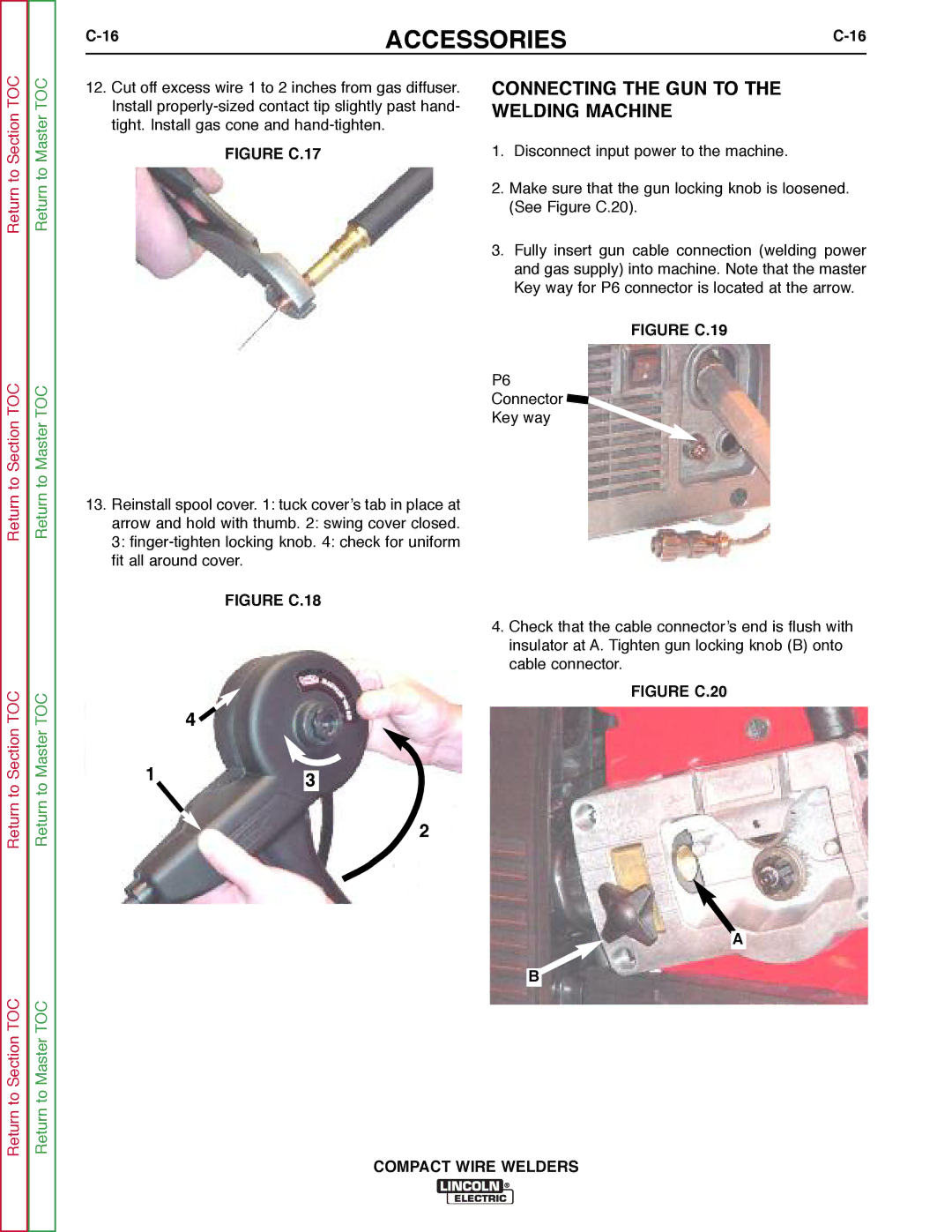
12.Cut off excess wire 1 to 2 inches from gas diffuser. Install
FIGURE C.17
CONNECTING THE GUN TO THE WELDING MACHINE
1.Disconnect input power to the machine.
2.Make sure that the gun locking knob is loosened. (See Figure C.20).
3.Fully insert gun cable connection (welding power and gas supply) into machine. Note that the master Key way for P6 connector is located at the arrow.
FIGURE C.19
Return to Section TOC
Return to Section TOC
to Section TOC
Return to Master TOC
to Master TOC
13.Reinstall spool cover. 1: tuck cover’s tab in place at
arrow and hold with thumb. 2: swing cover closed.
3:
FIGURE C.18
4 ![]()
13
P6
Connector ![]()
Key way
4.Check that the cable connector’s end is flush with insulator at A. Tighten gun locking knob (B) onto cable connector.
FIGURE C.20
Return
Return to Section TOC
Return
Return to Master TOC
2
A
B