Section TOC
Master TOC
ElEcTrical DiaGramS | ||
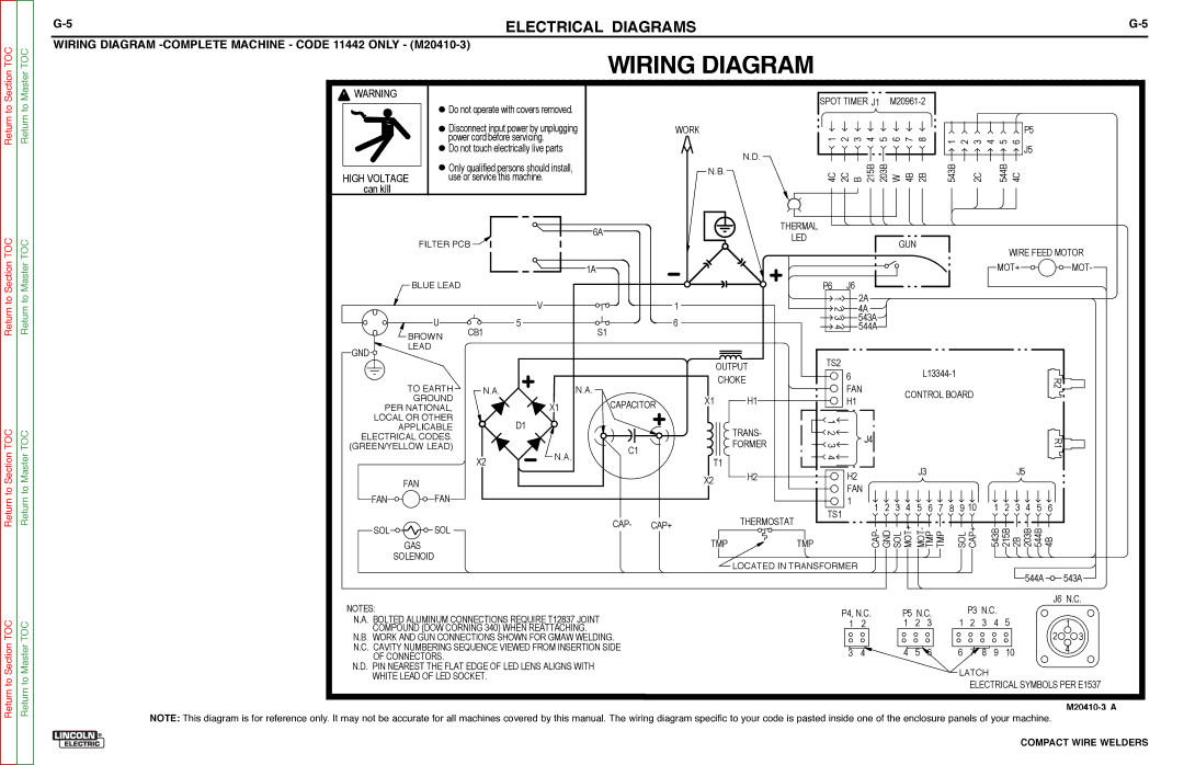
WiriNG DiaGram |
|
|
WIRING DIAGRAM
Return to
![]() WARNING
WARNING
HIGH VOLTAGE can kill
 Do not operate with covers removed.
![]()
![]()
![]()
![]() Disconnect input power by unplugging power cord before servicing.
Disconnect input power by unplugging power cord before servicing.
 Do not touch electrically live parts
![]()
![]()
![]()
![]() Only qualified persons should install, use or service this machine.
Only qualified persons should install, use or service this machine.
| SPOT TIMER J1 |
|
|
|
| |
WORK | 1 2 3 4 5 6 7 8 |
|
|
| P5 | |
| 1 2 3 4 5 | 6 | ||||
| N.D. |
|
|
|
| J5 |
| 215B 203B W 4B 2B | 543B | 2C | 544B | 4C | |
N.B. | 4C 2C B | |||||
|
|
|
|
|
| |
Return to Section TOC
Return to Master TOC
| FILTER PCB | 6A | |
|
| ||
|
|
| 1A |
| BLUE LEAD |
|
|
|
|
| V |
| U |
| 5 |
| BROWN | CB1 | S1 |
GND | LEAD |
|
|
|
|
| |
1
6
THERMAL
LED
P6 | J6 |
| 1 |
| 2 3 |
| 4 |
GUN
WIRE FEED MOTOR
MOT+ ![]()

![]()
![]()
![]()
![]()
![]()
![]()
![]()
![]()
![]()
![]() MOT-
MOT-
2A ![]()
![]()
![]() 4A
4A ![]()
![]()
![]()
![]() 543A
543A![]()
![]()
![]()
![]() 544A
544A
TO EARTH | N.A. |
| N.A. |
GROUND |
| X1 | CAPACITOR |
PER NATIONAL, |
|
| OUTPUT | TS2 | ||
| 6 | |||
| CHOKE | |||
X1 | H1 | FAN | CONTROL BOARD | |
H1 | ||||
|
R2![]()
![]()
TOC
TOC
LOCAL OR OTHER |
| D1 |
|
APPLICABLE |
|
| |
ELECTRICAL CODES. |
|
|
|
(GREEN/YELLOW LEAD) | X2 | N.A. | C1 |
|
| ||
|
|
|
![]()
![]()
![]() TRANS-
TRANS- ![]()
![]()
![]() FORMER
FORMER
T1
1 |
| |
2 | J4 | |
3 | ||
| ||
4 |
|
R1
Return to Section
Return to Master
| FAN |
|
|
FAN | FAN |
|
|
SOL | SOL | CAP- | CAP+ |
|
|
GAS
X2 H2
THERMOSTAT
TMP
H2
FAN
1
TS1
TMP
|
|
|
| J3 |
|
|
|
|
1 | 2 | 3 | 4 | 5 | 6 | 7 | 8 | 9 10 |
CAP- GND SOL MOT+ MOT- TMP TMP |
| SOL CAP+ | ||||||
|
| J5 |
|
|
|
1 | 2 | 3 | 4 | 5 | 6 |
543B 215B | 2B 203B 544B | 4B | |||
to Section TOC
Return to Master TOC
SOLENOID
NOTES:
N.A. BOLTED ALUMINUM CONNECTIONS REQUIRE T12837 JOINT COMPOUND (DOW CORNING 340) WHEN REATTACHING.
N.B. WORK AND GUN CONNECTIONS SHOWN FOR GMAW WELDING. N.C. CAVITY NUMBERING SEQUENCE VIEWED FROM INSERTION SIDE
OF CONNECTORS.
N.D. PIN NEAREST THE FLAT EDGE OF LED LENS ALIGNS WITH WHITE LEAD OF LED SOCKET.
LOCATED IN TRANSFORMER |
|
|
|
|
|
|
|
| 544A | 543A |
|
|
|
|
|
|
|
|
| ||
|
|
|
|
|
| P3 N.C. | J6 N.C. | |||
P4, N.C. | P5 N.C. | 1 | 5 | 1 | ||||||
1 | 2 | 1 | 2 | 3 | 2 | 3 | 4 | |||
|
|
|
|
|
|
|
|
| 2 | 3 |
3 | 4 | 4 | 5 | 6 | 6 | 7 | 8 | 9 | 10 | 4 |
|
|
|
|
| LATCH |
|
|
| ||
|
|
|
|
|
| ELECTRICAL SYMBOLS PER E1537 | ||||
Return
M20410-3 A
NOTE: This diagram is for reference only. It may not be accurate for all machines covered by this manual. The wiring diagram specific to your code is pasted inside one of the enclosure panels of your machine.