Return to Section TOC
Return to Section TOC
Return to Master TOC
Return to Master TOC
TROUBLESHOOTING & REPAIR | ||
|
CASE COVER REMOVAL AND REPLACEMENT PROCEDURE (CONTINUED)
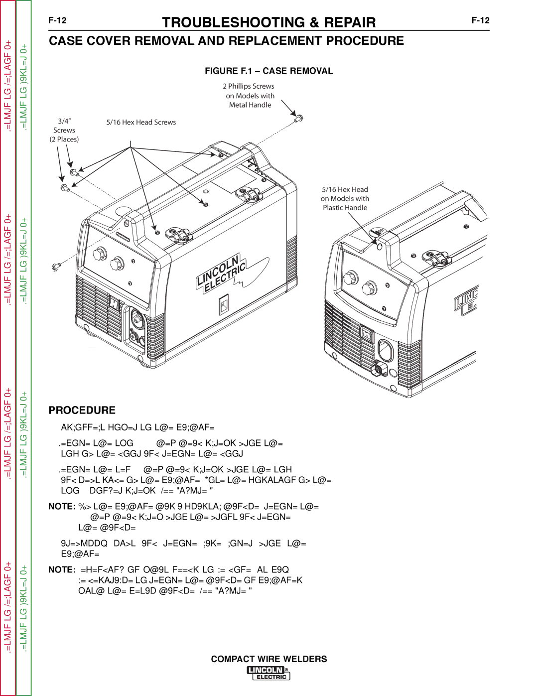
FIGURE F.1 – CASE REMOVAL
2 Phillips Screws
on Models with
Metal Handle
3/4” | 5/16 Hex Head Screws |
Screws |
|
(2 Places) |
|
5/16 Hex Head on Models with Plastic Handle
LINCOLN
ELECTRIC
Return to Section TOC
Return to Section TOC
Return to Master TOC
Return to Master TOC
PROCEDURE
1.Disconnect power to the machine.
2.Remove the two(2) 5/16
3.Remove the ten(10)
NOTE: If the machine has a plastic handle, remove the 5/16
4.Carefully lift and remove case cover from the machine.
NOTE: Depending on what needs to be done, it may be desirable to remove the handle on machines with the metal handle. See Figure F.1
