Section TOC
Master TOC
ElEcTrical DiaGramS | ||
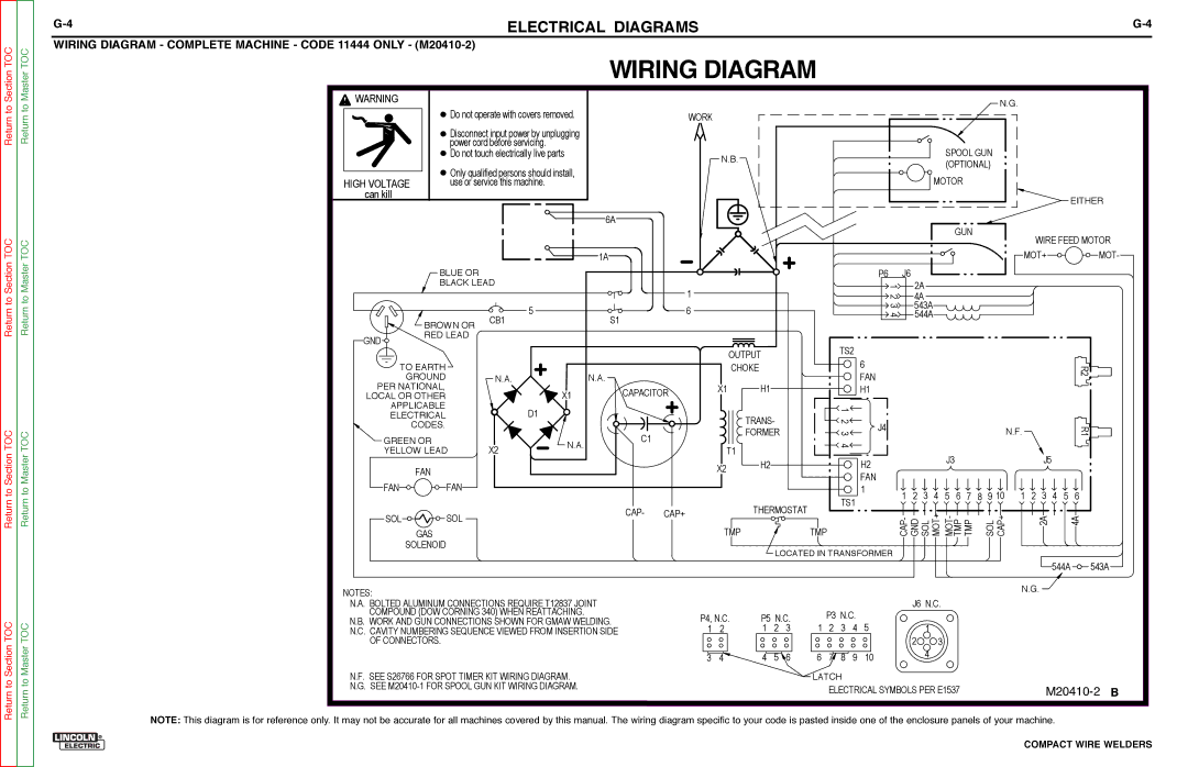
WiriNG DiaGram - cOmplETE machiNE - cODE 11444 ONly - |
|
|
WIRING DIAGRAM
Return to
![]() WARNING
WARNING
 Do not operate with covers removed.
![]()
![]()
![]() Disconnect input power by unplugging power cord before servicing.
Disconnect input power by unplugging power cord before servicing.
WORK
N.G.
Return to Section TOC
Return to Master TOC
HIGH VOLTAGE can kill
 Do not touch electrically live parts
![]()
![]()
![]()
![]() Only qualified persons should install, use or service this machine.
Only qualified persons should install, use or service this machine.
6A
1A
N.B.
SPOOL GUN (OPTIONAL)
MOTOR
GUN
![]() EITHER
EITHER
WIRE FEED MOTOR
MOT+ ![]()
![]()
![]()
![]()
![]()
![]()
![]()
![]()
![]()
![]()
![]() MOT-
MOT-
| BLUE OR |
|
|
| BLACK LEAD | 1 | |
|
|
| |
|
| 5 | 6 |
| BROWN OR | CB1 | S1 |
GND | RED LEAD |
|
|
|
|
| |
| TO EARTH |
|
|
| GROUND | N.A. | N.A. |
PER NATIONAL, |
|
| |
OUTPUT
CHOKE
X1 H1
P6 |
| J6 |
| 1 | 2A |
| 2 | 4A |
| 3 | 543A |
| 4 | 544A |
TS2
6
FAN
H1
R2![]()
![]()
Return to Section TOC
Return to Master TOC
LOCAL OR OTHER |
|
| X1 | CAPACITOR | |
APPLICABLE |
|
| D1 |
|
|
ELECTRICAL |
|
|
|
| |
CODES. |
|
|
| C1 |
|
GREEN OR |
| X2 | N.A. |
| |
YELLOW LEAD |
|
| |||
|
|
| |||
FAN |
|
|
|
|
|
FAN | FAN |
|
|
|
|
SOL | SOL |
|
| CAP- | CAP+ |
|
|
|
| ||
GAS
SOLENOID
![]()
![]()
![]() TRANS-
TRANS-
![]()
![]()
![]() FORMER
FORMER
T1
X2 H2
THERMOSTAT
TMP
1 |
| |
2 | J4 | |
3 | ||
| ||
4 |
| |
| H2 | |
| FAN | |
TS1 | 1 | |
|
TMP
|
|
|
|
|
|
|
|
| N.F. |
|
|
|
| R1 |
|
|
|
| J3 |
|
|
|
|
|
| J5 |
|
|
|
1 | 2 | 3 | 4 | 5 | 6 | 7 | 8 | 9 10 | 1 | 2 | 3 | 4 | 5 | 6 |
CAP- GND SOL MOT+ MOT- PTM TMP |
| SOL CAP+ |
|
| 2A |
|
| 4A | ||||||
NOTES:
LOCATED IN TRANSFORMER
![]() 544A
544A ![]()
![]()
![]()
![]() 543A
543A
N.G. ![]()
to Section TOC
to Master TOC
N.A. BOLTED ALUMINUM CONNECTIONS REQUIRE T12837 JOINT COMPOUND (DOW CORNING 340) WHEN REATTACHING.
N.B. WORK AND GUN CONNECTIONS SHOWN FOR GMAW WELDING. N.C. CAVITY NUMBERING SEQUENCE VIEWED FROM INSERTION SIDE
OF CONNECTORS.
N.F. SEE S26766 FOR SPOT TIMER KIT WIRING DIAGRAM.
P4, N.C. | P5 N.C. | |||
1 | 2 | 1 | 2 | 3 |
3 | 4 | 4 | 5 | 6 |
| P3 N.C. | 5 | ||
1 | 2 | 3 | 4 | |
6 | 7 | 8 | 9 | 10 |
LATCH
J6 N.C.
![]()
![]()
![]()
![]()
![]() 1
1![]()
![]()
![]()
![]()
![]() 2
2![]()
![]()
![]()
![]()
![]()
![]()
![]()
![]()
![]()
![]()
![]()
![]()
![]() 3
3![]()
![]()
![]()
![]()
![]()
![]()
![]()
![]() 4
4![]()
![]()
![]()
![]()
![]()
Return
Return
N.G. SEE
ELECTRICAL SYMBOLS PER E1537
NOTE: This diagram is for reference only. It may not be accurate for all machines covered by this manual. The wiring diagram specific to your code is pasted inside one of the enclosure panels of your machine.