Return to Section TOC
Return to Section TOC
Return to Master TOC
Return to Master TOC
TROUBLESHOOTING & REPAIR | ||
|
|
MAIN TRANSFORMER REMOVAL AND REPLACEMENT
(MACHINE CODES BELOW 10150)
(continued)
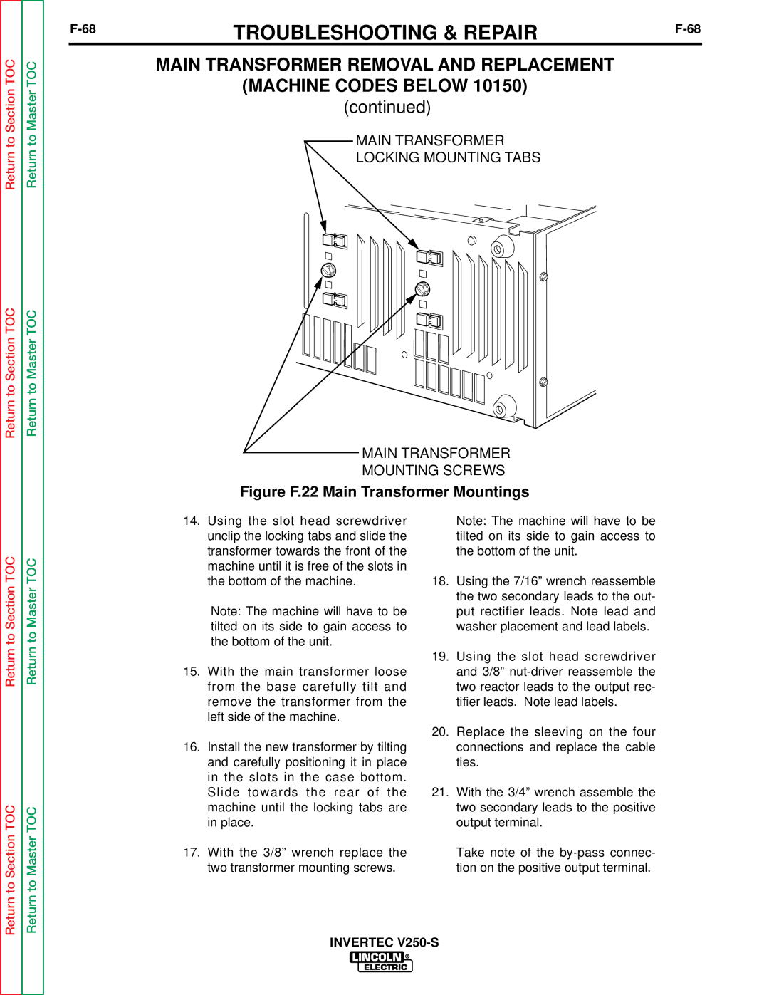
MAIN TRANSFORMER
LOCKING MOUNTING TABS
MAIN TRANSFORMER
MOUNTING SCREWS
Figure F.22 Main Transformer Mountings
Return to Section TOC
Return to Section TOC
Return to Master TOC
Return to Master TOC
14.Using the slot head screwdriver unclip the locking tabs and slide the transformer towards the front of the machine until it is free of the slots in the bottom of the machine.
Note: The machine will have to be tilted on its side to gain access to the bottom of the unit.
15.With the main transformer loose from the base carefully tilt and remove the transformer from the left side of the machine.
16.Install the new transformer by tilting and carefully positioning it in place in the slots in the case bottom. Slide towards the rear of the machine until the locking tabs are in place.
17.With the 3/8” wrench replace the two transformer mounting screws.
Note: The machine will have to be tilted on its side to gain access to the bottom of the unit.
18.Using the 7/16” wrench reassemble the two secondary leads to the out- put rectifier leads. Note lead and washer placement and lead labels.
19.Using the slot head screwdriver and 3/8”
20.Replace the sleeving on the four connections and replace the cable ties.
21.With the 3/4” wrench assemble the two secondary leads to the positive output terminal.
Take note of the