TOC
TOC
TROUBLESHOOTING & REPAIR | ||
|
|
AUXILIARY TRANSFORMER TEST (continued)
Return to Section
Return to Master
TEST PROCEDURE
1.Remove main input power to the
2.Perform Filter Capacitor Discharge Procedure detailed in Maintenance Section
3.Locate the Auxiliary Transformer just behind the input line switch on the lower right side of the machine.
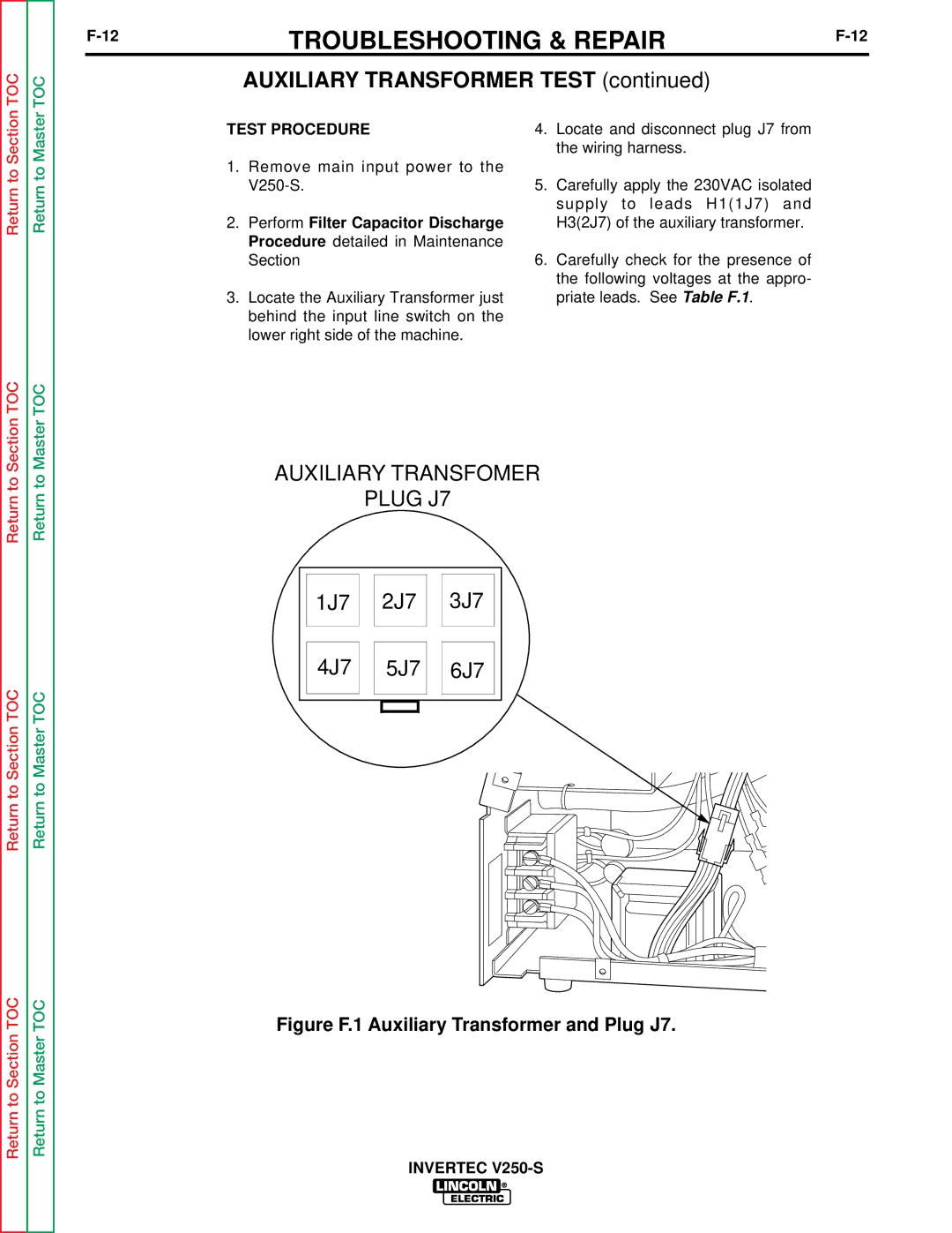
4.Locate and disconnect plug J7 from the wiring harness.
5.Carefully apply the 230VAC isolated supply to leads H1(1J7) and H3(2J7) of the auxiliary transformer.
6.Carefully check for the presence of the following voltages at the appro- priate leads. See Table F.1.
Return to Section TOC
Return to Section TOC
Return to Section TOC
Return to Master TOC
Return to Master TOC
Return to Master TOC
AUXILIARY TRANSFOMER
PLUG J7
1J7 ![]()
![]() 2J7
2J7 ![]()
![]() 3J7
3J7
4J7 ![]()
![]() 5J7
5J7 ![]()
![]() 6J7
6J7