TOC
TOC
TROUBLESHOOTING & REPAIR | ||
|
|
POWER BOARD RESISTANCE TEST (continued)
Return to Section
Return to Master
TEST DESCRIPTION
1.Remove main input power to the V250
2.Perform Filter Capacitor Discharge Procedure detailed in Maintenance Section.
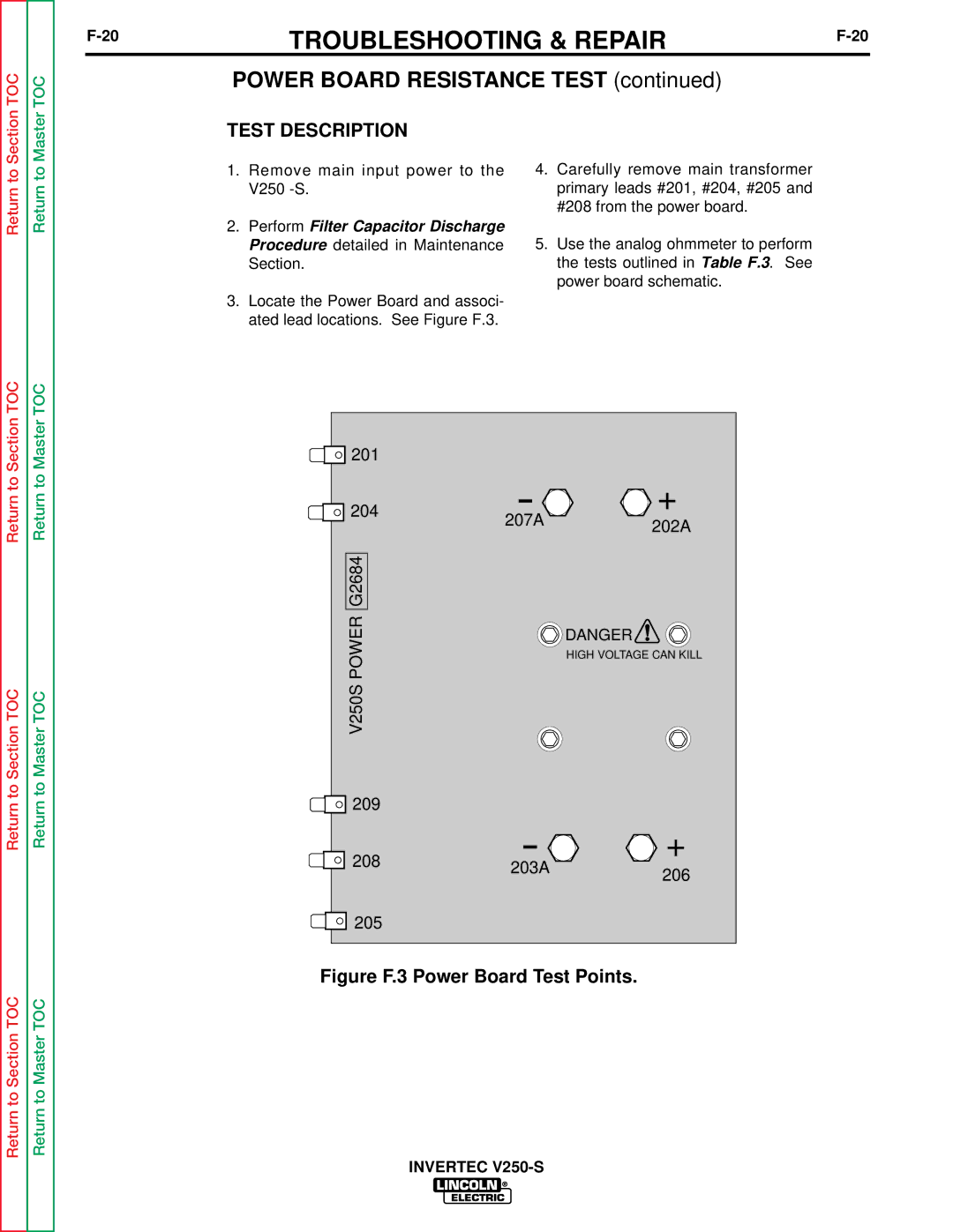
3.Locate the Power Board and associ- ated lead locations. See Figure F.3.
4.Carefully remove main transformer primary leads #201, #204, #205 and #208 from the power board.
5.Use the analog ohmmeter to perform the tests outlined in Table F.3. See power board schematic.
Return to Section TOC
Return to Section TOC
Return to Section TOC
Return to Master TOC
Return to Master TOC
Return to Master TOC
201 |
|
|
204 | 207A | + |
| 202A | |
|
| |
G2684 |
|
|
POWERV250S |
| DANGER |
|
|
HIGH VOLTAGE CAN KILL
![]()
![]()
![]() 209
209
208 | 203A | + | |
206 | |||
| |||
|
| ||
205 |
|
|