TOC
TOC
TROUBLESHOOTING & REPAIR | |
|
PROTECTION CIRCUIT TEST (continued)
Return to Section
Return to Section TOC
TOC
Return to Master
Return to Master TOC
TOC
4.The following tests will be performed with the input power applied to the
REMOVE INPUT POWER AND PERFORM FILTER CAPACITOR
DISCHARGE PROCEDURE
BEFORE TOUCHING ANY MACHINE COMPONENT.
5.Apply input power and turn ON the
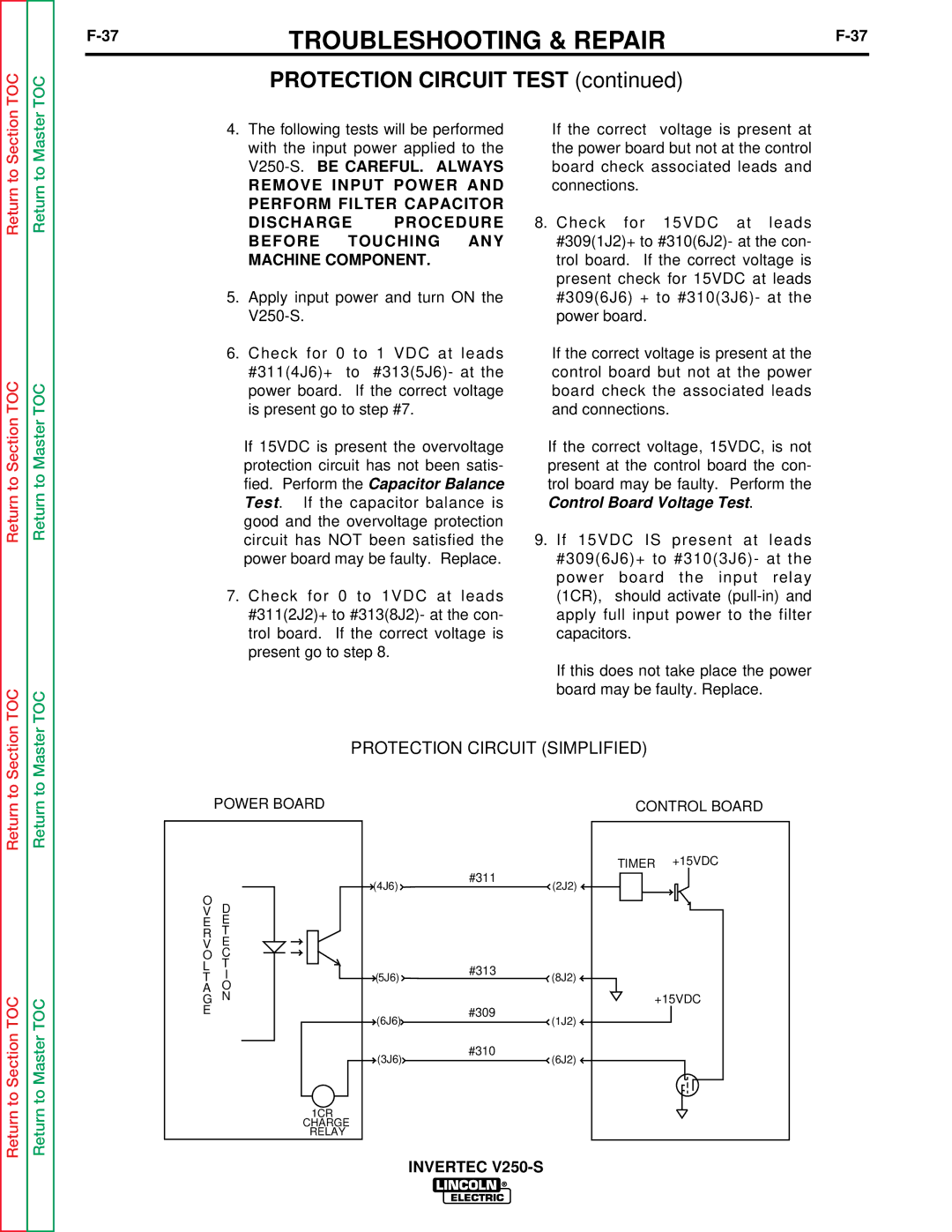
6.Check for 0 to 1 VDC at leads #311(4J6)+ to #313(5J6)- at the power board. If the correct voltage is present go to step #7.
If 15VDC is present the overvoltage protection circuit has not been satis- fied. Perform the Capacitor Balance Test. If the capacitor balance is good and the overvoltage protection circuit has NOT been satisfied the power board may be faulty. Replace.
7.Check for 0 to 1VDC at leads #311(2J2)+ to #313(8J2)- at the con- trol board. If the correct voltage is present go to step 8.
If the correct voltage is present at the power board but not at the control board check associated leads and connections.
8.Check for 15VDC at leads #309(1J2)+ to #310(6J2)- at the con- trol board. If the correct voltage is present check for 15VDC at leads #309(6J6) + to #310(3J6)- at the power board.
If the correct voltage is present at the control board but not at the power board check the associated leads and connections.
If the correct voltage, 15VDC, is not present at the control board the con- trol board may be faulty. Perform the Control Board Voltage Test.
9.If 15VDC IS present at leads #309(6J6)+ to #310(3J6)- at the power board the input relay (1CR), should activate
If this does not take place the power board may be faulty. Replace.
to Section
to Master